DVK-PRM112 Laird Technologies, DVK-PRM112 Datasheet - Page 13
DVK-PRM112
Manufacturer Part Number
DVK-PRM112
Description
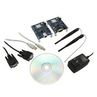
KIT FOR PRM112
Manufacturer
Laird Technologies
Series
FlexRF™r
Type
Transceiver, FHSSr
Specifications of DVK-PRM112
Frequency
2.4GHz
Output Power
50 mW
Antenna
U.FL Coaxial
Silicon Manufacturer
Laird Technologies
Kit Application Type
Communication & Networking
Application Sub Type
RF Module
Kit Contents
2x RF Module, 2x Adapter Board, CD, 2x AC Power Adapters, 2x DB9
Rohs Compliant
Yes
For Use With/related Products
PRM112
Lead Free Status / RoHS Status
Lead free / RoHS Compliant
Lead Free Status / RoHS Status
Lead free / RoHS Compliant, Lead free / RoHS Compliant
Available stocks
Company
Part Number
Manufacturer
Quantity
Price
Company:

Part Number:
DVK-PRM112
Manufacturer:
LAIRD
Quantity:
2


LT2510
Wireless Module
THEORY OF
OPERATION
10 www.lairdtech.com
SERIAL INTERFACE BAUD RATE
In order for the OEM Host and a transceiver to communicate over the serial interface they need to have the
same serial data rate. This value determines the baud rate used for communicating over the serial interface to a
transceiver. For a baud rate to be valid, the calculated baud rate must be within ±3% of the OEM Host baud rate
INTERFACE TIMEOUT/RF PACKET SIZE
Interface Timeout
Interface Timeout specifies a maximum byte gap between consecutive bytes. When that byte gap is exceeded,
the bytes in the transmit buffer are processed as a complete packet. Interface Timeout (EEPROM address 0x58), in
conjunction with the RF Packet Size, determines when a buffer of data will be sent out over the RF as a complete RF
packet, based on whichever condition occurs first. Interface Timeout is adjustable in 200us increments and should be
equal to or greater than two full bytes times. The minimum Interface Timeout is 0x02.
The radio will use the default Interface Timeout for a given baud rate if Auto Config is enabled, despite what is
written in the Interface Timeout address. To use a non-standard Interface Timeout, the OEM would need to disable
Auto Config.
TABLE 7: BAUD RATE/INTERFACE TIMEOUT
1
2
For baud rates other than those shown in Table 7 the following equations can be used:
Where:
FREQUENCY = 26 MHz
BAUD_M = EEPROM Address 0x43
BAUD_E = EEPROM Address 0x44
DESIRED BAND RATE
230,400
115,200
57,600
38,400
28,000
19,200
14,400
9,600
4,800
2,400
1,200
Non-standard
• The LT2510 supports a majority of standard as well as non-standard baud rates. To select a standard baud
• Adjusting the Serial Interface Baud Rate does not affect the RF data rate.
• Radio can accept Serial combinations (number of bits, Parity, Number of Stop Bits) of 8-N-1, 7-N-2, 7-1-1,
ENGINEER’S TIP
rate, use the value shown for EEPROM address 0x42 in Table 7 above. To enable a non-standard baud
rate, program EEPROM address 0x42 (Custom Baud Enable) to 0xE3 and then use the equation above to
solve for BAUD_M and BAUD_E.
by Default. Modes of 8-1-1, 8-N-2, 7-1-2 are acceptable with 9-bit mode enabled.
Interface Timeout = 200uS per increment, the EEPROM address 0x58 is ignored if Auto Config is enabled. To use a non-standard
Interface Timeout, disable Auto Config.
Default baud rate.
2
Baud Rate =
Minimum Interface Timeout =
BAUD (0x42)
0x0A
0x09
0x08
0x07
0x06
0x05
0x04
0x03
0x02
0x01
0x00
0xE3
(256 + BAUD_M) * (2
2
28
BAUD_E
Baud Rate
MINIMUM INTERFACE TIMEOUT
100,000
) * FREQUENCY
Use equation below
0x02
0x02
0x02
0x02
0x03
0x05
0x07
0x10
0x15
0x2A
0x53
1
(0x58)
Laird Technologies
Related parts for DVK-PRM112
Image
Part Number
Description
Manufacturer
Datasheet
Request
R

Part Number:
Description:
BLUETOOTH EVAL BOARD BTM511
Manufacturer:
Laird Technologies
Datasheet:

Part Number:
Description:
Bluetooth / 802.15.1 Modules & Development Tools BLUETTH AT Data MODLE, No ANT DEVKIT
Manufacturer:
Laird Technologies
Part Number:
Description:
Bluetooth / 802.15.1 Modules & Development Tools BLUETTH Multimed MODLE, No ANT DEVKIT
Manufacturer:
Laird Technologies
Datasheet:

Part Number:
Description:
BLUETOOTH MODULE DEVELOPMENT KIT
Manufacturer:
Laird Technologies
Part Number:
Description:
Bluetooth 2.0 AT Data Module, Internal Antenna Development Kit
Manufacturer:
Laird Technologies

Part Number:
Description:
BT MM DEV KIT
Manufacturer:
Laird Technologies
Datasheet:
Part Number:
Description:
Bluetooth / 802.15.1 Modules & Development Tools BLUETTH HCI Data MDLE INTRNLANT DVKIT
Manufacturer:
Laird Technologies
Datasheet:
Part Number:
Description:
Bluetooth / 802.15.1 Modules & Development Tools BLUETTHMultimedMODLE Plus No Ant DEVKIT
Manufacturer:
Laird Technologies
Part Number:
Description:
Bluetooth / 802.15.1 Modules & Development Tools BLUETTH HCI Data MDLE No ANT DVKIT
Manufacturer:
Laird Technologies
Datasheet:

Part Number:
Description:
KIT FOR PRM113
Manufacturer:
Laird Technologies
Datasheet:

Part Number:
Description:
DEV KIT PRM122
Manufacturer:
Laird Technologies
Datasheet:
Part Number:
Description:
DEV KIT PRM123
Manufacturer:
Laird Technologies
Datasheet:
Part Number:
Description:
DEV KIT PRM121
Manufacturer:
Laird Technologies
Datasheet:

Part Number:
Description:
KIT DEVELOPMENT FOR LT2510 U.FL
Manufacturer:
Laird Technologies
Datasheet:

Part Number:
Description:
Bluetooth / 802.15.1 Modules Class2 v2.1+EDR Kit AT Data, Int Ant,SSP
Manufacturer:
Laird Technologies Wireless M2M
Datasheet: