DVK-PRM112 Laird Technologies, DVK-PRM112 Datasheet - Page 11
DVK-PRM112
Manufacturer Part Number
DVK-PRM112
Description
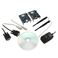
KIT FOR PRM112
Manufacturer
Laird Technologies
Series
FlexRF™r
Type
Transceiver, FHSSr
Specifications of DVK-PRM112
Frequency
2.4GHz
Output Power
50 mW
Antenna
U.FL Coaxial
Silicon Manufacturer
Laird Technologies
Kit Application Type
Communication & Networking
Application Sub Type
RF Module
Kit Contents
2x RF Module, 2x Adapter Board, CD, 2x AC Power Adapters, 2x DB9
Rohs Compliant
Yes
For Use With/related Products
PRM112
Lead Free Status / RoHS Status
Lead free / RoHS Compliant
Lead Free Status / RoHS Status
Lead free / RoHS Compliant, Lead free / RoHS Compliant
Available stocks
Company
Part Number
Manufacturer
Quantity
Price
Company:

Part Number:
DVK-PRM112
Manufacturer:
LAIRD
Quantity:
2


LT2510
Wireless Module
THEORY OF
OPERATION
8
www.lairdtech.com
SERVER/CLIENT ARCHITECTURE
The LT2510 utilizes a server-client network architecture to synchronize the frequency hopping. Each network must
have one radio configured as a Server and all other radios configured as Clients. When a radio is configured as a
Server, it will transmit a beacon containing timing and identification information at the beginning of each hop. The
beacon is never visible to the OEM host. Upon boot, radios configured as Clients will enter receive mode where they
are scanning the available frequencies listening for a beacon from a Server in their network. When a Client detects
the Server’s beacon, the client will synchronize it’s frequency hopping to that of the Server and transition the InRange
pin Low. When the Server and the Client are synchronized they can begin transferring data.
Each network consists of one, and only one, Server. Multiple networks can exist in the same area, provided the
networks are configured on different Channels. The LT2510 utilizes an intelligent Frequency Hopping algorithm
which ensures minimal interference between networks. The possible interference between collocated networks is
given by the equation.
For example, with 10 collocated networks, there will be up to 9 bins every hop cycle that are occupied by more than
one network at the same time. Although two or more networks might occupy the same hop bin at the same time,
there will truly only be interference if two or more radios from alternate networks are trying to transmit on the same
bin at the same time in the same coverage area.
1
Deciding which RF Data Rate to choose depends on the individual application. The fast RF Data Rate will deliver
much faster throughput, but will have much less range. In addition, because the lower data rate solution uses more
hops, it is better situated for collocated networks. In firmware version 1.2-5 and above the RF Data rate is set by the
appropriate RF Profile, EEPROM Address 0x54.
A rule of thumb for RF systems is every 6dB of gain doubles the effective distance. The 4dB increase of Receive
Sensitivity for the lower data rate solution means it will be able to transmit almost 60% farther than the higher data
rate solution.
ADJUSTABLE RF DATA RATE
The LT2510’s RF data rate can be adjusted to provide a trade-off between throughput and range.
TABLE 6: RF DATA RATE
PRODUCT MODEL
PRM110, 111, 112, 113,
120, 121, 122, 123
PRM110, 111, 120, 121
PRM110, 111, 112, 113,
120, 121, 122, 123
Throughput is ideal, one direction, with no retransmissions. All practical RF applications should allow for the retransmission of data due to
interference or less than ideal RF conditions.
Maximum number of interfering bins = # of collocated Servers -1
RF PROFILE
0x00
0x01
0x03
RF DATA RATE NUMBER OF HOPS RECEIVER SENSITIVITY
500 kbps
280 kbps
280 kbps
43
79
43
-94 dBm
-98 dBm
-98 dBm
Laird Technologies
THROUGHPUT
250 kbps
120 kbps
120 kbps
1
Related parts for DVK-PRM112
Image
Part Number
Description
Manufacturer
Datasheet
Request
R

Part Number:
Description:
BLUETOOTH EVAL BOARD BTM511
Manufacturer:
Laird Technologies
Datasheet:

Part Number:
Description:
Bluetooth / 802.15.1 Modules & Development Tools BLUETTH AT Data MODLE, No ANT DEVKIT
Manufacturer:
Laird Technologies
Part Number:
Description:
Bluetooth / 802.15.1 Modules & Development Tools BLUETTH Multimed MODLE, No ANT DEVKIT
Manufacturer:
Laird Technologies
Datasheet:

Part Number:
Description:
BLUETOOTH MODULE DEVELOPMENT KIT
Manufacturer:
Laird Technologies
Part Number:
Description:
Bluetooth 2.0 AT Data Module, Internal Antenna Development Kit
Manufacturer:
Laird Technologies

Part Number:
Description:
BT MM DEV KIT
Manufacturer:
Laird Technologies
Datasheet:
Part Number:
Description:
Bluetooth / 802.15.1 Modules & Development Tools BLUETTH HCI Data MDLE INTRNLANT DVKIT
Manufacturer:
Laird Technologies
Datasheet:
Part Number:
Description:
Bluetooth / 802.15.1 Modules & Development Tools BLUETTHMultimedMODLE Plus No Ant DEVKIT
Manufacturer:
Laird Technologies
Part Number:
Description:
Bluetooth / 802.15.1 Modules & Development Tools BLUETTH HCI Data MDLE No ANT DVKIT
Manufacturer:
Laird Technologies
Datasheet:

Part Number:
Description:
KIT FOR PRM113
Manufacturer:
Laird Technologies
Datasheet:

Part Number:
Description:
DEV KIT PRM122
Manufacturer:
Laird Technologies
Datasheet:
Part Number:
Description:
DEV KIT PRM123
Manufacturer:
Laird Technologies
Datasheet:
Part Number:
Description:
DEV KIT PRM121
Manufacturer:
Laird Technologies
Datasheet:

Part Number:
Description:
KIT DEVELOPMENT FOR LT2510 U.FL
Manufacturer:
Laird Technologies
Datasheet:

Part Number:
Description:
Bluetooth / 802.15.1 Modules Class2 v2.1+EDR Kit AT Data, Int Ant,SSP
Manufacturer:
Laird Technologies Wireless M2M
Datasheet: