M30620FCAFP#D5 Renesas Electronics America, M30620FCAFP#D5 Datasheet - Page 555
M30620FCAFP#D5
Manufacturer Part Number
M30620FCAFP#D5
Description
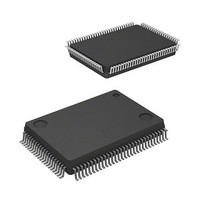
IC M16C MCU FLASH 128K 100LQFP
Manufacturer
Renesas Electronics America
Series
M16C™ M16C/60r
Specifications of M30620FCAFP#D5
Core Processor
M16C/60
Core Size
16-Bit
Speed
16MHz
Connectivity
SIO, UART/USART
Peripherals
DMA, PWM, WDT
Number Of I /o
85
Program Memory Size
128KB (128K x 8)
Program Memory Type
FLASH
Ram Size
10K x 8
Voltage - Supply (vcc/vdd)
4.2 V ~ 5.5 V
Data Converters
A/D 10x10b, D/A 2x8b
Oscillator Type
Internal
Operating Temperature
-20°C ~ 85°C
Package / Case
100-LQFP
Lead Free Status / RoHS Status
Contains lead / RoHS non-compliant
Eeprom Size
-
Available stocks
Company
Part Number
Manufacturer
Quantity
Price

Part Number:
M30620FCAFP#D5M30620FCAFP#D3
Manufacturer:
Renesas Electronics America
Quantity:
10 000


External Buses
2-236
Figure 4.4.3. Relation of processor mode and the wait bit (PM17, CSiW) (1)
4.4.2 Connecting Low-Speed Memory
To connect memory with long access time [ta(A)], either decrease the frequency of BCLK or set a soft-
ware wait. Using the RDY feature allows you to connect memory having the timing that precludes con-
nection though you set software wait.
(1) Using software wait
In case of M30620MAA
FFFFF
Set software wait by using either of bit 7 (PM17) of processor mode register 1 or bits 4 through 7
(CS0W through CS3W) of the chip select control register. With software wait set, if an address space
is accessed in which a separate bus is selected, the bus cycle results in two cycles of BCLK; if an
address space is accessed in which a multiplex bus is selected, the bus cycle results in three cycles of
BCLK.
If bit 7 (PM17) of processor mode register 1 is set to “Wait selected”, the microcomputer accesses
every area with this option in effect. If bit 7 (PM17) of processor mode register 1 is set to “Wait
cleared”, the Wait option can be either selected or cleared, chip select by chip select, by setting bits
4 through 7 (CS0W through CS3W) of the chip select control register. Figures 4.4.3 through 4.4.5
show relation of processor mode and the wait bit (PM17, CSiW).
02C00
E8000
00000
00400
16
16
16
16
16
(When, PM17 = “0”)
Single-chip mode
Internal ROM area
Internal RAM area
SFR area
________
BCLK X 2
BCLK X 1
BCLK X 1
FFFFF
02C00
E8000
00000
00400
16
16
16
16
16
(When, PM17 = “1”)
Single-chip mode
Internal ROM area
Internal RAM area
SINGLE-CHIP 16-BIT CMOS MICROCOMPUTER
SFR area
M16C / 62A Group
Mitsubishi microcomputers
BCLK X 2
BCLK X 2
BCLK X 2
Related parts for M30620FCAFP#D5
Image
Part Number
Description
Manufacturer
Datasheet
Request
R

Part Number:
Description:
KIT STARTER FOR M16C/29
Manufacturer:
Renesas Electronics America
Datasheet:

Part Number:
Description:
KIT STARTER FOR R8C/2D
Manufacturer:
Renesas Electronics America
Datasheet:

Part Number:
Description:
R0K33062P STARTER KIT
Manufacturer:
Renesas Electronics America
Datasheet:

Part Number:
Description:
KIT STARTER FOR R8C/23 E8A
Manufacturer:
Renesas Electronics America
Datasheet:

Part Number:
Description:
KIT STARTER FOR R8C/25
Manufacturer:
Renesas Electronics America
Datasheet:

Part Number:
Description:
KIT STARTER H8S2456 SHARPE DSPLY
Manufacturer:
Renesas Electronics America
Datasheet:

Part Number:
Description:
KIT STARTER FOR R8C38C
Manufacturer:
Renesas Electronics America
Datasheet:

Part Number:
Description:
KIT STARTER FOR R8C35C
Manufacturer:
Renesas Electronics America
Datasheet:

Part Number:
Description:
KIT STARTER FOR R8CL3AC+LCD APPS
Manufacturer:
Renesas Electronics America
Datasheet:
Part Number:
Description:
KIT STARTER FOR RX610
Manufacturer:
Renesas Electronics America
Datasheet:

Part Number:
Description:
KIT STARTER FOR R32C/118
Manufacturer:
Renesas Electronics America
Datasheet:

Part Number:
Description:
KIT DEV RSK-R8C/26-29
Manufacturer:
Renesas Electronics America
Datasheet:

Part Number:
Description:
KIT STARTER FOR SH7124
Manufacturer:
Renesas Electronics America
Datasheet:

Part Number:
Description:
KIT STARTER FOR H8SX/1622
Manufacturer:
Renesas Electronics America
Datasheet:

Part Number:
Description:
KIT DEV FOR SH7203
Manufacturer:
Renesas Electronics America
Datasheet: