M30620FCAFP#D5 Renesas Electronics America, M30620FCAFP#D5 Datasheet - Page 416
M30620FCAFP#D5
Manufacturer Part Number
M30620FCAFP#D5
Description
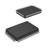
IC M16C MCU FLASH 128K 100LQFP
Manufacturer
Renesas Electronics America
Series
M16C™ M16C/60r
Specifications of M30620FCAFP#D5
Core Processor
M16C/60
Core Size
16-Bit
Speed
16MHz
Connectivity
SIO, UART/USART
Peripherals
DMA, PWM, WDT
Number Of I /o
85
Program Memory Size
128KB (128K x 8)
Program Memory Type
FLASH
Ram Size
10K x 8
Voltage - Supply (vcc/vdd)
4.2 V ~ 5.5 V
Data Converters
A/D 10x10b, D/A 2x8b
Oscillator Type
Internal
Operating Temperature
-20°C ~ 85°C
Package / Case
100-LQFP
Lead Free Status / RoHS Status
Contains lead / RoHS non-compliant
Eeprom Size
-
Available stocks
Company
Part Number
Manufacturer
Quantity
Price

Part Number:
M30620FCAFP#D5M30620FCAFP#D3
Manufacturer:
Renesas Electronics America
Quantity:
10 000


UART
Figure 2.5.17. Operation timing of reception in UART mode (used for SIM interface)
Transfer clock
Receive enable
bit
R
T
Signal line level
(Note)
Receive
complete flag
Receive interrupt
request bit
X
X
(RE)
D
Example of wiring
Example of operation (when direct format)
D
2
2
(Note)
(Note)
(IR)
Note: TxD
(RI)
become the same signal from the logical standpoint, but the output signals turn complex, so they are shown separately. Also,
the signal level resulting from connecting TxD
“1”
“0”
“1”
“0”
“1”
“0”
The above timing applies to the following settings :
2
Shown in ( ) are bit symbols.
(1) Reception enabled
and RxD
• Parity is enabled.
• One stop bit.
• Transmit interrupt cause select bit = “1”.
Microcomputer
(2) Start reception
2
ST
ST
Start
are connected in the manner of wired OR as shown in the connection diagram. So TxD
bit
D
D
0
0
D
D
1
1
Tc
RxD
TxD
D
D
2
2
D
D
3
3
D
D
2
2
4
4
D
D
5
5
D
D
2
6
6
Cleared to “0” when interrupt request is accepted, or cleared by software
and RxD
D
D
Parity
7
7
bit
P
P
(3) Receiving is completed
2
SP
SP
Tc = 16 (n + 1) / fi
is shown as a signal line level.
Stop
bit
(4) Data is read
Read to receive buffer
fi : frequency of BRG2 count source (f
n : value set to BRG2
ST
ST
Since a parity error occurred, the
“L” level returns from TxD
D
D
0
0
D
D
1
1
D
D
SIM card
SINGLE-CHIP 16-BIT CMOS MICROCOMPUTER
2
2
D
D
3
3
D
D
4
4
D
D
5
5
2
D
D
1
6
6
, f
2
D
D
8
, f
and RxD
7
7
32
P
P
)
(5) Parity error occurred
M16C / 62A Group
Read to receive buffer
SP
SP
Mitsubishi microcomputers
2
ought to
2-97
Related parts for M30620FCAFP#D5
Image
Part Number
Description
Manufacturer
Datasheet
Request
R

Part Number:
Description:
KIT STARTER FOR M16C/29
Manufacturer:
Renesas Electronics America
Datasheet:

Part Number:
Description:
KIT STARTER FOR R8C/2D
Manufacturer:
Renesas Electronics America
Datasheet:

Part Number:
Description:
R0K33062P STARTER KIT
Manufacturer:
Renesas Electronics America
Datasheet:

Part Number:
Description:
KIT STARTER FOR R8C/23 E8A
Manufacturer:
Renesas Electronics America
Datasheet:

Part Number:
Description:
KIT STARTER FOR R8C/25
Manufacturer:
Renesas Electronics America
Datasheet:

Part Number:
Description:
KIT STARTER H8S2456 SHARPE DSPLY
Manufacturer:
Renesas Electronics America
Datasheet:

Part Number:
Description:
KIT STARTER FOR R8C38C
Manufacturer:
Renesas Electronics America
Datasheet:

Part Number:
Description:
KIT STARTER FOR R8C35C
Manufacturer:
Renesas Electronics America
Datasheet:

Part Number:
Description:
KIT STARTER FOR R8CL3AC+LCD APPS
Manufacturer:
Renesas Electronics America
Datasheet:
Part Number:
Description:
KIT STARTER FOR RX610
Manufacturer:
Renesas Electronics America
Datasheet:

Part Number:
Description:
KIT STARTER FOR R32C/118
Manufacturer:
Renesas Electronics America
Datasheet:

Part Number:
Description:
KIT DEV RSK-R8C/26-29
Manufacturer:
Renesas Electronics America
Datasheet:

Part Number:
Description:
KIT STARTER FOR SH7124
Manufacturer:
Renesas Electronics America
Datasheet:

Part Number:
Description:
KIT STARTER FOR H8SX/1622
Manufacturer:
Renesas Electronics America
Datasheet:

Part Number:
Description:
KIT DEV FOR SH7203
Manufacturer:
Renesas Electronics America
Datasheet: