M30620FCAFP#D5 Renesas Electronics America, M30620FCAFP#D5 Datasheet - Page 425
M30620FCAFP#D5
Manufacturer Part Number
M30620FCAFP#D5
Description
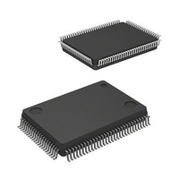
IC M16C MCU FLASH 128K 100LQFP
Manufacturer
Renesas Electronics America
Series
M16C™ M16C/60r
Specifications of M30620FCAFP#D5
Core Processor
M16C/60
Core Size
16-Bit
Speed
16MHz
Connectivity
SIO, UART/USART
Peripherals
DMA, PWM, WDT
Number Of I /o
85
Program Memory Size
128KB (128K x 8)
Program Memory Type
FLASH
Ram Size
10K x 8
Voltage - Supply (vcc/vdd)
4.2 V ~ 5.5 V
Data Converters
A/D 10x10b, D/A 2x8b
Oscillator Type
Internal
Operating Temperature
-20°C ~ 85°C
Package / Case
100-LQFP
Lead Free Status / RoHS Status
Contains lead / RoHS non-compliant
Eeprom Size
-
Available stocks
Company
Part Number
Manufacturer
Quantity
Price

Part Number:
M30620FCAFP#D5M30620FCAFP#D3
Manufacturer:
Renesas Electronics America
Quantity:
10 000


SI/O3, 4
2-106
2.6 SI/O3, 4 Usage
Figure 2.6.1. Memory map of serial I/O3, 4-related registers
2.6.1 Overview of the SI/O3,4 usage
SI/O3, 4 carries out 8-bit data communications in synchronization with the clock. The following is an
overview of the SI/O3, 4 usage.
(1) Transmission/reception format
(2) Transfer rate
(3) Function selection
(6) Input to the serial I/O and the direction register
(7) Pins related to the SI/O3, 4
(8) Registers related to the SI/O3, 4
8-bit data
If the internal clock is selected as the transfer clock, the divide-by-2 frequency, resulting from the bit
rate generator division, becomes the transfer rate. The bit rate generator count source can be se-
lected from the following: f
clock by 1, 8, and 32 respectively.
Furthermore, if an external clock is selected as the transfer clock, the clock frequency input to the CLK
pin becomes the transfer rate.
For SI/O3, 4, the following functions can be selected:
(a) Function for choosing which bit to transmit first
(b) Choosing output level when not transferring
To input an external signal to the serial I/O, set the direction register of the relevant port to input.
• CLK3, CLK4 pins
• S
• S
Figure 2.6.1 shows the memory map of SI/O3, 4-related registers, and Figures 2.6.2 show SI/O3, 4-
related registers.
This function is to choose whether to transmit data from bit 0 or from bit 7. Choose either of the
following:
• LSB first
• MSB first
• Internal clock
• External clock
IN3
OUT3
, S
, S
IN4
OUT4
pins
0048
0049
0360
0361
0362
0363
0364
0365
0366
0367
Data is transmitted from bit 0.
Data is transmitted from bit 7.
pins Output pins for data
16
16
16
16
16
16
16
16
16
16
SI/O3 transmit/receive control register (S3C)
SI/O4 transmit/receive register (S4TRR)
SI/O4 interrupt control register (S4IC)
SI/O3 interrupt control register (S3IC)
SI/O3 transmit/receive register (S3TRR)
SI/O4 control register (S4C)
SI/O3
SI/O4
High-impedance output.
"H" or "L" output level is selected.
Input/output pins for the transfer clock
Input pins for data
1
, f
bit rate generator (S3BRG)
bit rate generator (S4BRG)
8
, and f
32
. Clocks f
1
, f
8
, and f
32
are derived by dividing the CPU’s main
SINGLE-CHIP 16-BIT CMOS MICROCOMPUTER
M16C / 62A Group
Mitsubishi microcomputers
Related parts for M30620FCAFP#D5
Image
Part Number
Description
Manufacturer
Datasheet
Request
R

Part Number:
Description:
KIT STARTER FOR M16C/29
Manufacturer:
Renesas Electronics America
Datasheet:

Part Number:
Description:
KIT STARTER FOR R8C/2D
Manufacturer:
Renesas Electronics America
Datasheet:

Part Number:
Description:
R0K33062P STARTER KIT
Manufacturer:
Renesas Electronics America
Datasheet:

Part Number:
Description:
KIT STARTER FOR R8C/23 E8A
Manufacturer:
Renesas Electronics America
Datasheet:

Part Number:
Description:
KIT STARTER FOR R8C/25
Manufacturer:
Renesas Electronics America
Datasheet:

Part Number:
Description:
KIT STARTER H8S2456 SHARPE DSPLY
Manufacturer:
Renesas Electronics America
Datasheet:

Part Number:
Description:
KIT STARTER FOR R8C38C
Manufacturer:
Renesas Electronics America
Datasheet:

Part Number:
Description:
KIT STARTER FOR R8C35C
Manufacturer:
Renesas Electronics America
Datasheet:

Part Number:
Description:
KIT STARTER FOR R8CL3AC+LCD APPS
Manufacturer:
Renesas Electronics America
Datasheet:
Part Number:
Description:
KIT STARTER FOR RX610
Manufacturer:
Renesas Electronics America
Datasheet:

Part Number:
Description:
KIT STARTER FOR R32C/118
Manufacturer:
Renesas Electronics America
Datasheet:

Part Number:
Description:
KIT DEV RSK-R8C/26-29
Manufacturer:
Renesas Electronics America
Datasheet:

Part Number:
Description:
KIT STARTER FOR SH7124
Manufacturer:
Renesas Electronics America
Datasheet:

Part Number:
Description:
KIT STARTER FOR H8SX/1622
Manufacturer:
Renesas Electronics America
Datasheet:

Part Number:
Description:
KIT DEV FOR SH7203
Manufacturer:
Renesas Electronics America
Datasheet: