M30620FCAFP#D5 Renesas Electronics America, M30620FCAFP#D5 Datasheet - Page 501
M30620FCAFP#D5
Manufacturer Part Number
M30620FCAFP#D5
Description
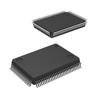
IC M16C MCU FLASH 128K 100LQFP
Manufacturer
Renesas Electronics America
Series
M16C™ M16C/60r
Specifications of M30620FCAFP#D5
Core Processor
M16C/60
Core Size
16-Bit
Speed
16MHz
Connectivity
SIO, UART/USART
Peripherals
DMA, PWM, WDT
Number Of I /o
85
Program Memory Size
128KB (128K x 8)
Program Memory Type
FLASH
Ram Size
10K x 8
Voltage - Supply (vcc/vdd)
4.2 V ~ 5.5 V
Data Converters
A/D 10x10b, D/A 2x8b
Oscillator Type
Internal
Operating Temperature
-20°C ~ 85°C
Package / Case
100-LQFP
Lead Free Status / RoHS Status
Contains lead / RoHS non-compliant
Eeprom Size
-
Available stocks
Company
Part Number
Manufacturer
Quantity
Price

Part Number:
M30620FCAFP#D5M30620FCAFP#D3
Manufacturer:
Renesas Electronics America
Quantity:
10 000


Programmable I/O Ports
2-182
Table 2.16.1. Relation between ports and I/O functions of built-in peripheral devices
Table 2.16.2. Examples of working on unused pins in single-chip mode
Note 1:
Note 2:
Note 3:
Ports P0 to P10 (excluding P8
X
AV
NMI
AV
P7
P1
P7
P7
P7
P7
P8
P9
P9
P6
P8
P8
P9
P9
P10
P10
OUT
(6) I/O functions of built-in peripheral devices
(7) Examples of working on non-used pins
CC
SS
0
1
4
6
7
5
2
0
2
6
0
3
5
, P8
, P8
, P9
, P9
Table 2.16.1 shows relation between ports and I/O functions of built-in peripheral devices.
0
4
Table 2.16.2 contains examples of working on non-used pins. There are shown here for mere ex-
amples. In practical use, make suitable changes and perform sufficient evaluation in compliance with
you application.
(a) Single-chip mode
to P7
to P7
to P1
to P7
to P8
to P9
, V
(Note 2)
to P10
to P10
If setting these pins in output mode and opening them, ports are in input mode until switched into
output mode by use of software after reset. Thus the voltage levels of the pins become unstable,
and there can be instances in which the power source current increases while the ports are in
input mode.
In view of an instance in which the contents of the direction registers change due to a runaway
generated by noise or other causes, setting the contents of the direction registers periodically by
use of software increases program reliability.
When an external clock is input to the X
Output "L" if port P7
Port P7
Port
REF
1
7
4
6
5
7
7
3
4
2
Pin name
, BYTE
3
7
0
and P7
Input pins for external interrupt
I/O pins for serial I/O communication
I/O pins for serial I/O communication/Timer A I/O pins/Three-phase motor
control output pins
Timer A I/O pins
Input pins for external interrupt
Sub-clock oscillation circuit I/O pins
A-D converter input pins
A-D converter input pins / key-input interrupt function input pins
1
I/O pins for serial I/O communication/Timer A I/O pin
I/O pins for serial I/O communication/Timer A I/O pins/Timer B input pin
Timer A I/O pins/Three-phase motor control output pins
Timer A I/O pins
Timer B input pins
D-A converter output pins
A-D converter extended input pins
A-D trigger input pin
are N channel open drain output.
0
and P7
5
)
After setting for input mode, connect every pin to V
resistor; or after setting for output mode, leave these pins open.
(Note 1, Note 3)
Connect to V
Connect to V
Connect to V
Open
1
are set to output mode.
Internal peripheral device I/O pins
SS
CC
CC
IN
pin.
via a resistor
Connection
SINGLE-CHIP 16-BIT CMOS MICROCOMPUTER
SS
M16C / 62A Group
or V
Mitsubishi microcomputers
CC
via a
Related parts for M30620FCAFP#D5
Image
Part Number
Description
Manufacturer
Datasheet
Request
R

Part Number:
Description:
KIT STARTER FOR M16C/29
Manufacturer:
Renesas Electronics America
Datasheet:

Part Number:
Description:
KIT STARTER FOR R8C/2D
Manufacturer:
Renesas Electronics America
Datasheet:

Part Number:
Description:
R0K33062P STARTER KIT
Manufacturer:
Renesas Electronics America
Datasheet:

Part Number:
Description:
KIT STARTER FOR R8C/23 E8A
Manufacturer:
Renesas Electronics America
Datasheet:

Part Number:
Description:
KIT STARTER FOR R8C/25
Manufacturer:
Renesas Electronics America
Datasheet:

Part Number:
Description:
KIT STARTER H8S2456 SHARPE DSPLY
Manufacturer:
Renesas Electronics America
Datasheet:

Part Number:
Description:
KIT STARTER FOR R8C38C
Manufacturer:
Renesas Electronics America
Datasheet:

Part Number:
Description:
KIT STARTER FOR R8C35C
Manufacturer:
Renesas Electronics America
Datasheet:

Part Number:
Description:
KIT STARTER FOR R8CL3AC+LCD APPS
Manufacturer:
Renesas Electronics America
Datasheet:
Part Number:
Description:
KIT STARTER FOR RX610
Manufacturer:
Renesas Electronics America
Datasheet:

Part Number:
Description:
KIT STARTER FOR R32C/118
Manufacturer:
Renesas Electronics America
Datasheet:

Part Number:
Description:
KIT DEV RSK-R8C/26-29
Manufacturer:
Renesas Electronics America
Datasheet:

Part Number:
Description:
KIT STARTER FOR SH7124
Manufacturer:
Renesas Electronics America
Datasheet:

Part Number:
Description:
KIT STARTER FOR H8SX/1622
Manufacturer:
Renesas Electronics America
Datasheet:

Part Number:
Description:
KIT DEV FOR SH7203
Manufacturer:
Renesas Electronics America
Datasheet: