M30620FCAFP#D5 Renesas Electronics America, M30620FCAFP#D5 Datasheet - Page 403
M30620FCAFP#D5
Manufacturer Part Number
M30620FCAFP#D5
Description
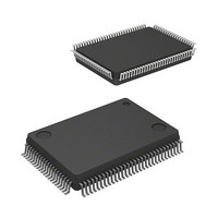
IC M16C MCU FLASH 128K 100LQFP
Manufacturer
Renesas Electronics America
Series
M16C™ M16C/60r
Specifications of M30620FCAFP#D5
Core Processor
M16C/60
Core Size
16-Bit
Speed
16MHz
Connectivity
SIO, UART/USART
Peripherals
DMA, PWM, WDT
Number Of I /o
85
Program Memory Size
128KB (128K x 8)
Program Memory Type
FLASH
Ram Size
10K x 8
Voltage - Supply (vcc/vdd)
4.2 V ~ 5.5 V
Data Converters
A/D 10x10b, D/A 2x8b
Oscillator Type
Internal
Operating Temperature
-20°C ~ 85°C
Package / Case
100-LQFP
Lead Free Status / RoHS Status
Contains lead / RoHS non-compliant
Eeprom Size
-
Available stocks
Company
Part Number
Manufacturer
Quantity
Price

Part Number:
M30620FCAFP#D5M30620FCAFP#D3
Manufacturer:
Renesas Electronics America
Quantity:
10 000


UART
2-84
Operation
2.5.2 Operation of Serial I/O (transmission in UART mode)
In transmitting data in UART mode, choose functions from those listed in Table 2.5.4. Operations of the
circled items are described below. Figure 2.5.8 shows the operation timing, and Figures 2.5.9 and 2.5.10
show the set-up procedures.
Table 2.5.4. Choosed functions
Note 1: UART0, UART1 only.
Note 2: UART2 only.
(1) Setting the transmit enable bit to “1” and writing transmission data to the UARTi transmit
(2) When input to the CTSi pin goes to “L”, transmission starts (the CTSi pin needs to be con-
(3) Transmission data held in the UARTi transmit buffer register is transmitted to the UARTi
(4) When the stop bit(s) is (are) transmitted, the transmit register empty flag goes to “1”, which
(5) If the transmission condition of the next data is ready when transmission is completed, a start
Transfer clock
source
(Note 1)
Transmission
interrupt factor
CTS function
buffer register readies the data transmissible status.
trolled on the reception side).
transmit register. At this time, the first bit (the start bit) of the transmission data is transmitted
from the TxDi pin. Then, data is transmitted, bit by bit, in sequence: LSB, ····, MSB, parity bit,
and stop bit(s).
indicates that transmission is completed. At this time, the UARTi transmit interrupt request bit
goes to “1”. The transfer clock stops at “H” level.
bit is generated following to stop bit(s), and the next data is transmitted.
Item
O
O
O
________
CTS function disabled
Transmission complete
Internal clock (f
External clock (CLKi pin)
CTS function enabled
Transmission buffer empty
Set-up
1
/ f
8
/ f
32
)
Sleep mode
(Note 1)
Data logic select
function
(Note 2)
T
polarity reverse bit
(Note 2)
Bus collision
detection function
(Note 2)
X
D, R
X
Item
D I/O
SINGLE-CHIP 16-BIT CMOS MICROCOMPUTER
O
O
O
O
________
Sleep mode off
No reverse
Reverse
No reverse
Reverse
Not selected
Sleep mode selected
Selected
M16C / 62A Group
Mitsubishi microcomputers
Set-up
Related parts for M30620FCAFP#D5
Image
Part Number
Description
Manufacturer
Datasheet
Request
R

Part Number:
Description:
KIT STARTER FOR M16C/29
Manufacturer:
Renesas Electronics America
Datasheet:

Part Number:
Description:
KIT STARTER FOR R8C/2D
Manufacturer:
Renesas Electronics America
Datasheet:

Part Number:
Description:
R0K33062P STARTER KIT
Manufacturer:
Renesas Electronics America
Datasheet:

Part Number:
Description:
KIT STARTER FOR R8C/23 E8A
Manufacturer:
Renesas Electronics America
Datasheet:

Part Number:
Description:
KIT STARTER FOR R8C/25
Manufacturer:
Renesas Electronics America
Datasheet:

Part Number:
Description:
KIT STARTER H8S2456 SHARPE DSPLY
Manufacturer:
Renesas Electronics America
Datasheet:

Part Number:
Description:
KIT STARTER FOR R8C38C
Manufacturer:
Renesas Electronics America
Datasheet:

Part Number:
Description:
KIT STARTER FOR R8C35C
Manufacturer:
Renesas Electronics America
Datasheet:

Part Number:
Description:
KIT STARTER FOR R8CL3AC+LCD APPS
Manufacturer:
Renesas Electronics America
Datasheet:
Part Number:
Description:
KIT STARTER FOR RX610
Manufacturer:
Renesas Electronics America
Datasheet:

Part Number:
Description:
KIT STARTER FOR R32C/118
Manufacturer:
Renesas Electronics America
Datasheet:

Part Number:
Description:
KIT DEV RSK-R8C/26-29
Manufacturer:
Renesas Electronics America
Datasheet:

Part Number:
Description:
KIT STARTER FOR SH7124
Manufacturer:
Renesas Electronics America
Datasheet:

Part Number:
Description:
KIT STARTER FOR H8SX/1622
Manufacturer:
Renesas Electronics America
Datasheet:

Part Number:
Description:
KIT DEV FOR SH7203
Manufacturer:
Renesas Electronics America
Datasheet: