M30620FCAFP#D5 Renesas Electronics America, M30620FCAFP#D5 Datasheet - Page 515
M30620FCAFP#D5
Manufacturer Part Number
M30620FCAFP#D5
Description
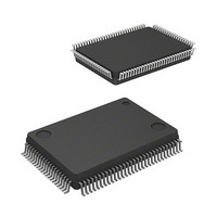
IC M16C MCU FLASH 128K 100LQFP
Manufacturer
Renesas Electronics America
Series
M16C™ M16C/60r
Specifications of M30620FCAFP#D5
Core Processor
M16C/60
Core Size
16-Bit
Speed
16MHz
Connectivity
SIO, UART/USART
Peripherals
DMA, PWM, WDT
Number Of I /o
85
Program Memory Size
128KB (128K x 8)
Program Memory Type
FLASH
Ram Size
10K x 8
Voltage - Supply (vcc/vdd)
4.2 V ~ 5.5 V
Data Converters
A/D 10x10b, D/A 2x8b
Oscillator Type
Internal
Operating Temperature
-20°C ~ 85°C
Package / Case
100-LQFP
Lead Free Status / RoHS Status
Contains lead / RoHS non-compliant
Eeprom Size
-
Available stocks
Company
Part Number
Manufacturer
Quantity
Price

Part Number:
M30620FCAFP#D5M30620FCAFP#D3
Manufacturer:
Renesas Electronics America
Quantity:
10 000


Timer A Applications
2-196
Overview
Specifications
Operation
3.2 Variable-Period Variable-Duty PWM Output
In this process, Timer A0 and A1 are used to generate variable-period, variable-duty PWM out-
put. Figure 3.2.1 shows the operation timing, Figure 3.2.2 shows the connection diagram, and
Figures 3.2.3 and 3.2.4 show the set-up procedure.
Use the following peripheral functions:
(1) Set timer A0 in timer mode, and set timer A1 in one-shot timer mode with pulse-output function.
(2) Set 1 ms, the PWM period, to timer A0. Set 500 s, the width of PWM “H” pulse, to timer A1.
(3) Connect a 16-MHz oscillator to X
(1) Setting the count start flag to “1” causes the counter of timer A0 to begin counting. The
(2) If the counter of timer A0 underflows, the counter reloads the content of the reload register
(3) An underflow in timer A0 triggers the counter of timer A1 and causes it to begin counting. When
(4) As soon as the count of the counter of timer A1 becomes “0000
• Timer mode of timer A
• One-shot timer mode of timer A
Both timer A0 and timer A1 use f
counter of timer A0 performs a down count on count source f
and continues counting. At this time, the timer A0 interrupt request bit goes to “1”.
the counter of timer A1 begins counting, the output level of the TA1
pin goes to “L”, and the counter reloads the content of the reload register and stops counting.
At the same time, the timer A1 interrupt request bit goes to “1”.
1
IN
for the count source.
.
SINGLE-CHIP 16-BIT CMOS MICROCOMPUTER
1
16
.
”, the output level of TA1
OUT
pin goes to “H”.
M16C / 62A Group
Mitsubishi microcomputers
OUT
Related parts for M30620FCAFP#D5
Image
Part Number
Description
Manufacturer
Datasheet
Request
R

Part Number:
Description:
KIT STARTER FOR M16C/29
Manufacturer:
Renesas Electronics America
Datasheet:

Part Number:
Description:
KIT STARTER FOR R8C/2D
Manufacturer:
Renesas Electronics America
Datasheet:

Part Number:
Description:
R0K33062P STARTER KIT
Manufacturer:
Renesas Electronics America
Datasheet:

Part Number:
Description:
KIT STARTER FOR R8C/23 E8A
Manufacturer:
Renesas Electronics America
Datasheet:

Part Number:
Description:
KIT STARTER FOR R8C/25
Manufacturer:
Renesas Electronics America
Datasheet:

Part Number:
Description:
KIT STARTER H8S2456 SHARPE DSPLY
Manufacturer:
Renesas Electronics America
Datasheet:

Part Number:
Description:
KIT STARTER FOR R8C38C
Manufacturer:
Renesas Electronics America
Datasheet:

Part Number:
Description:
KIT STARTER FOR R8C35C
Manufacturer:
Renesas Electronics America
Datasheet:

Part Number:
Description:
KIT STARTER FOR R8CL3AC+LCD APPS
Manufacturer:
Renesas Electronics America
Datasheet:
Part Number:
Description:
KIT STARTER FOR RX610
Manufacturer:
Renesas Electronics America
Datasheet:

Part Number:
Description:
KIT STARTER FOR R32C/118
Manufacturer:
Renesas Electronics America
Datasheet:

Part Number:
Description:
KIT DEV RSK-R8C/26-29
Manufacturer:
Renesas Electronics America
Datasheet:

Part Number:
Description:
KIT STARTER FOR SH7124
Manufacturer:
Renesas Electronics America
Datasheet:

Part Number:
Description:
KIT STARTER FOR H8SX/1622
Manufacturer:
Renesas Electronics America
Datasheet:

Part Number:
Description:
KIT DEV FOR SH7203
Manufacturer:
Renesas Electronics America
Datasheet: