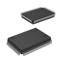
M30620FCAFP#D5 Renesas Electronics America, M30620FCAFP#D5 Datasheet - Page 342

M30620FCAFP#D5
Manufacturer Part Number
M30620FCAFP#D5
Description
IC M16C MCU FLASH 128K 100LQFP
Manufacturer
Renesas Electronics America
Series
M16C™ M16C/60r
Specifications of M30620FCAFP#D5
Core Processor
M16C/60
Core Size
16-Bit
Speed
16MHz
Connectivity
SIO, UART/USART
Peripherals
DMA, PWM, WDT
Number Of I /o
85
Program Memory Size
128KB (128K x 8)
Program Memory Type
FLASH
Ram Size
10K x 8
Voltage - Supply (vcc/vdd)
4.2 V ~ 5.5 V
Data Converters
A/D 10x10b, D/A 2x8b
Oscillator Type
Internal
Operating Temperature
-20°C ~ 85°C
Package / Case
100-LQFP
Lead Free Status / RoHS Status
Contains lead / RoHS non-compliant
Eeprom Size
-
Available stocks
Company
Part Number
Manufacturer
Quantity
Price
Part Number:
M30620FCAFP#D5M30620FCAFP#D3
Manufacturer:
Renesas Electronics America
Quantity:
10 000
- Current page: 342 of 617
- Download datasheet (9Mb)
Timer A
Figure 2.2.17. Set-up procedure of 2-phase pulse signal process in event counter mode, normal mode selected
(b15)
Setting counter value
Setting count start flag
Setting trigger select register
b7
b7
b7
Selecting event counter mode and functions
b7
Setting two-phase pulse signal processing select bit
b7
0
Note 2: Set the TAi
Note 3: Set the corresponding port direction register to “0”.
Note 1: This bit is valid for timer A3 mode register. For timer A2 mode register, this bit can be “0” or “1”.
1
0
1
0
0
IN
, TAi
0
b0
b0
(b8)
b0
b0
1
b0
OUT
Selection of event counter mode
0 (Must always be “0” when using two-phase pulse signal processing)
Count operation type select bit
Two-phase pulse signal processing operation select bit (Note 1)
b7
Timer A2 count start flag
Timer A3 count start flag
0 (Must always be “0” when using two-phase pulse signal processing)
1 (Must always be “1” when using two-phase pulse signal processing)
0 (Must always be “0” when using two-phase pulse signal processing)
Timer A2 two-phase pulse signal processing select bit (Note 2)
Timer A3 two-phase pulse signal processing select bit (Note 2)
Trigger select register [Address 0383
TRGSR
Count start flag [Address 0380
TABSR
Timer A2 event/trigger select bit
Timer A3 event/trigger select bit
1 : Free-run type
0 : Normal processing operation
b3 b2
b5 b4
1 : Two-phase pulse signal processing enabled
1 : Two-phase pulse signal processing enabled
0 0 : Input on TA2
0 0 : Input on TA3
Up/down flag [Address 0384
UDF
corresponding port direction register to “0”.
Timer Ai mode register (i= 2, 3) [Address 0398
TAiMR (i= 2, 3)
Can be set to 0000
Start count
IN
IN
is selected (Note 3)
is selected (Note 3)
b0
16
16
16
Timer A2 register [Address 038B
Timer A3 register [Address 038D
to FFFF
]
]
16
16
]
SINGLE-CHIP 16-BIT CMOS MICROCOMPUTER
16
, 0399
16
]
16
16
, 038A
, 038C
M16C / 62A Group
Mitsubishi microcomputers
16
16
] TA2
] TA3
2-23
Related parts for M30620FCAFP#D5
Image
Part Number
Description
Manufacturer
Datasheet
Request
R

Part Number:
Description:
KIT STARTER FOR M16C/29
Manufacturer:
Renesas Electronics America
Datasheet:

Part Number:
Description:
KIT STARTER FOR R8C/2D
Manufacturer:
Renesas Electronics America
Datasheet:

Part Number:
Description:
R0K33062P STARTER KIT
Manufacturer:
Renesas Electronics America
Datasheet:

Part Number:
Description:
KIT STARTER FOR R8C/23 E8A
Manufacturer:
Renesas Electronics America
Datasheet:

Part Number:
Description:
KIT STARTER FOR R8C/25
Manufacturer:
Renesas Electronics America
Datasheet:

Part Number:
Description:
KIT STARTER H8S2456 SHARPE DSPLY
Manufacturer:
Renesas Electronics America
Datasheet:

Part Number:
Description:
KIT STARTER FOR R8C38C
Manufacturer:
Renesas Electronics America
Datasheet:

Part Number:
Description:
KIT STARTER FOR R8C35C
Manufacturer:
Renesas Electronics America
Datasheet:

Part Number:
Description:
KIT STARTER FOR R8CL3AC+LCD APPS
Manufacturer:
Renesas Electronics America
Datasheet:

Part Number:
Description:
KIT STARTER FOR RX610
Manufacturer:
Renesas Electronics America
Datasheet:

Part Number:
Description:
KIT STARTER FOR R32C/118
Manufacturer:
Renesas Electronics America
Datasheet:

Part Number:
Description:
KIT DEV RSK-R8C/26-29
Manufacturer:
Renesas Electronics America
Datasheet:

Part Number:
Description:
KIT STARTER FOR SH7124
Manufacturer:
Renesas Electronics America
Datasheet:

Part Number:
Description:
KIT STARTER FOR H8SX/1622
Manufacturer:
Renesas Electronics America
Datasheet:

Part Number:
Description:
KIT DEV FOR SH7203
Manufacturer:
Renesas Electronics America
Datasheet:


