M30620FCAFP#D5 Renesas Electronics America, M30620FCAFP#D5 Datasheet - Page 385
M30620FCAFP#D5
Manufacturer Part Number
M30620FCAFP#D5
Description
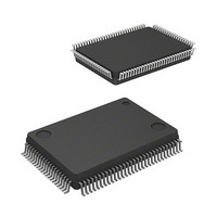
IC M16C MCU FLASH 128K 100LQFP
Manufacturer
Renesas Electronics America
Series
M16C™ M16C/60r
Specifications of M30620FCAFP#D5
Core Processor
M16C/60
Core Size
16-Bit
Speed
16MHz
Connectivity
SIO, UART/USART
Peripherals
DMA, PWM, WDT
Number Of I /o
85
Program Memory Size
128KB (128K x 8)
Program Memory Type
FLASH
Ram Size
10K x 8
Voltage - Supply (vcc/vdd)
4.2 V ~ 5.5 V
Data Converters
A/D 10x10b, D/A 2x8b
Oscillator Type
Internal
Operating Temperature
-20°C ~ 85°C
Package / Case
100-LQFP
Lead Free Status / RoHS Status
Contains lead / RoHS non-compliant
Eeprom Size
-
Available stocks
Company
Part Number
Manufacturer
Quantity
Price

Part Number:
M30620FCAFP#D5M30620FCAFP#D3
Manufacturer:
Renesas Electronics America
Quantity:
10 000


Clock-Synchronous Serial I/O
2-66
Figure 2.4.11. Set-up procedure of transmission in clock-synchronous serial I/O mode, transfer
b7
Setting UART1 transmit/receive mode register
b7
Setting UART1 transmit/receive control register 0
Setting UART transmit/receive control register 2
b7
0
0
0
0
clock output from multiple pins function selected (1)
1
1
0
0
1
0
b0
b0
b0
1
Must be fixed to “001”
Invalid in clock synchronous I/O mode
Invalid in clock synchronous I/O mode
Transfer format select bit
Internal/external clock select bit
Invalid in clock synchronous I/O mode
Sleep select bit
BRG count source select bit
Valid when bit 4 = “0”
Transmit register empty flag
CTS/RTS disable bit
Data output select bit
CLK polarity select bit
UART0 transmit interrupt cause select bit
CLK/CLKS select bit 0
Reserved bit
CLK/CLKS select bit 1
b1 b0
0 : Internal clock
Must always be “0” in clock synchronous I/O mode
1 : CTS/RTS function disabled
0 : LSB first
0 0 : f
0 1 : f
1 0 : f
1 1 : Must not be set
0 : Data present in transmit register (during transmission)
1 : No data present in transmit register (transmission completed)
0 : T
1 : TxDi pin is N-channel open-drain output
1 : Transmission completed (TXEPT = 1)
Must always be set to “0”
0 : Transmission data is output at falling edge of transfer clock and
0 : Clock output to CLK1
1 : Clock output to CLKS1
1 : Transfer clock output from multiple pins function selected
UART transmit/receive control register 2 [Address 03B0
UCON
UART1 transmit/receive mode register [Address 03A8
U1MR
UART1 transmit/receive control register 0 [Address 03AC
U1C0
reception data is input at rising edge
X
1
8
32
Di pin is CMOS output
is selected
is selected
is selected
Continued to the next page
SINGLE-CHIP 16-BIT CMOS MICROCOMPUTER
16
16
]
16
]
]
M16C / 62A Group
Mitsubishi microcomputers
Related parts for M30620FCAFP#D5
Image
Part Number
Description
Manufacturer
Datasheet
Request
R

Part Number:
Description:
KIT STARTER FOR M16C/29
Manufacturer:
Renesas Electronics America
Datasheet:

Part Number:
Description:
KIT STARTER FOR R8C/2D
Manufacturer:
Renesas Electronics America
Datasheet:

Part Number:
Description:
R0K33062P STARTER KIT
Manufacturer:
Renesas Electronics America
Datasheet:

Part Number:
Description:
KIT STARTER FOR R8C/23 E8A
Manufacturer:
Renesas Electronics America
Datasheet:

Part Number:
Description:
KIT STARTER FOR R8C/25
Manufacturer:
Renesas Electronics America
Datasheet:

Part Number:
Description:
KIT STARTER H8S2456 SHARPE DSPLY
Manufacturer:
Renesas Electronics America
Datasheet:

Part Number:
Description:
KIT STARTER FOR R8C38C
Manufacturer:
Renesas Electronics America
Datasheet:

Part Number:
Description:
KIT STARTER FOR R8C35C
Manufacturer:
Renesas Electronics America
Datasheet:

Part Number:
Description:
KIT STARTER FOR R8CL3AC+LCD APPS
Manufacturer:
Renesas Electronics America
Datasheet:
Part Number:
Description:
KIT STARTER FOR RX610
Manufacturer:
Renesas Electronics America
Datasheet:

Part Number:
Description:
KIT STARTER FOR R32C/118
Manufacturer:
Renesas Electronics America
Datasheet:

Part Number:
Description:
KIT DEV RSK-R8C/26-29
Manufacturer:
Renesas Electronics America
Datasheet:

Part Number:
Description:
KIT STARTER FOR SH7124
Manufacturer:
Renesas Electronics America
Datasheet:

Part Number:
Description:
KIT STARTER FOR H8SX/1622
Manufacturer:
Renesas Electronics America
Datasheet:

Part Number:
Description:
KIT DEV FOR SH7203
Manufacturer:
Renesas Electronics America
Datasheet: