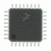
MC56F8011VFAE Freescale Semiconductor, MC56F8011VFAE Datasheet - Page 46

MC56F8011VFAE
Manufacturer Part Number
MC56F8011VFAE
Description
IC DIGITAL SIGNAL CTLR 32-LQFP
Manufacturer
Freescale Semiconductor
Series
56F8xxxr
Datasheet
1.MC56F8013VFAE.pdf
(126 pages)
Specifications of MC56F8011VFAE
Core Processor
56800
Core Size
16-Bit
Speed
32MHz
Connectivity
I²C, SCI, SPI
Peripherals
POR, PWM, WDT
Number Of I /o
26
Program Memory Size
12KB (6K x 16)
Program Memory Type
FLASH
Ram Size
1K x 16
Voltage - Supply (vcc/vdd)
3 V ~ 3.6 V
Data Converters
A/D 6x12b
Oscillator Type
Internal
Operating Temperature
-40°C ~ 105°C
Package / Case
32-LQFP
Product
DSCs
Data Bus Width
16 bit
Processor Series
MC56F80xx
Core
56800E
Numeric And Arithmetic Format
Fixed-Point
Device Million Instructions Per Second
32 MIPs
Maximum Clock Frequency
32 MHz
Number Of Programmable I/os
26
Data Ram Size
2 KB
Operating Supply Voltage
3.3 V
Maximum Operating Temperature
+ 105 C
Mounting Style
SMD/SMT
Development Tools By Supplier
MC56F8037EVM, DEMO56F8014-EE, DEMO56F8013-EE
Interface Type
SCI, SPI, I2C
Minimum Operating Temperature
- 40 C
For Use With
CPA56F8013 - BOARD SOCKET FOR MC56F8013APMOTOR56F8000E - KIT DEMO MOTOR CTRL SYSTEM
Lead Free Status / RoHS Status
Lead free / RoHS Compliant
Eeprom Size
-
Lead Free Status / Rohs Status
Lead free / RoHS Compliant
Available stocks
Company
Part Number
Manufacturer
Quantity
Price
Company:
Part Number:
MC56F8011VFAE
Manufacturer:
Freescale
Quantity:
1
Company:
Part Number:
MC56F8011VFAE
Manufacturer:
Freescale Semiconductor
Quantity:
10 000
5.3.1
Once the INTC has determined that an interrupt is to be serviced and which interrupt has the highest
priority, an interrupt vector address is generated. Normal interrupt handling concatenates the Vector Base
Address (VBA) and the vector number to determine the vector address, generating an offset into the vector
table for each interrupt.
5.3.2
Interrupt exceptions may be nested to allow an IRQ of higher priority than the current exception to be
serviced. The following table defines the nesting requirements for each priority level.
5.3.3
Fast interrupts are described in the DSP56800E Reference Manual. The interrupt controller recognizes
Fast Interrupts before the core does.
A Fast Interrupt is defined (to the ITCN) by:
When an interrupt occurs, its vector number is compared with the FIM0 and FIM1 register values. If a
match occurs, and it is a level 2 interrupt, the ITCN handles it as a Fast Interrupt. The ITCN takes the vector
address from the appropriate FIVALn and FIVAHn registers, instead of generating an address that is an
offset from the VBA.
The core then fetches the instruction from the indicated vector adddress and if it is not a JSR, the core starts
its Fast Interrupt handling.
46
1. Setting the priority of the interrupt as level 2, with the appropriate field in the IPR registers
2. Setting the FIMn register to the appropriate vector number
3. Setting the FIVALn and FIVAHn registers with the address of the code for the
Normal Interrupt Handling
Interrupt Nesting
Fast Interrupt Handling
SR[9]
0
0
1
1
Table 5-1 Interrupt Mask Bit Definition
SR[8]
0
1
0
1
56F8013/56F8011 Data Sheet, Rev. 12
Exceptions Permitted
Priorities 0, 1, 2, 3
Priorities 1, 2, 3
Priorities 2, 3
Priority 3
Exceptions Masked
Priorities 0, 1, 2
Priorities 0, 1
Priority 0
None
Fast Interrupt
Freescale Semiconductor


