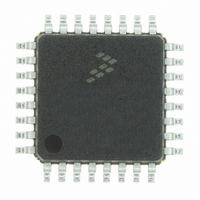
MC56F8011VFAE Freescale Semiconductor, MC56F8011VFAE Datasheet - Page 120

MC56F8011VFAE
Manufacturer Part Number
MC56F8011VFAE
Description
IC DIGITAL SIGNAL CTLR 32-LQFP
Manufacturer
Freescale Semiconductor
Series
56F8xxxr
Datasheet
1.MC56F8013VFAE.pdf
(126 pages)
Specifications of MC56F8011VFAE
Core Processor
56800
Core Size
16-Bit
Speed
32MHz
Connectivity
I²C, SCI, SPI
Peripherals
POR, PWM, WDT
Number Of I /o
26
Program Memory Size
12KB (6K x 16)
Program Memory Type
FLASH
Ram Size
1K x 16
Voltage - Supply (vcc/vdd)
3 V ~ 3.6 V
Data Converters
A/D 6x12b
Oscillator Type
Internal
Operating Temperature
-40°C ~ 105°C
Package / Case
32-LQFP
Product
DSCs
Data Bus Width
16 bit
Processor Series
MC56F80xx
Core
56800E
Numeric And Arithmetic Format
Fixed-Point
Device Million Instructions Per Second
32 MIPs
Maximum Clock Frequency
32 MHz
Number Of Programmable I/os
26
Data Ram Size
2 KB
Operating Supply Voltage
3.3 V
Maximum Operating Temperature
+ 105 C
Mounting Style
SMD/SMT
Development Tools By Supplier
MC56F8037EVM, DEMO56F8014-EE, DEMO56F8013-EE
Interface Type
SCI, SPI, I2C
Minimum Operating Temperature
- 40 C
For Use With
CPA56F8013 - BOARD SOCKET FOR MC56F8013APMOTOR56F8000E - KIT DEMO MOTOR CTRL SYSTEM
Lead Free Status / RoHS Status
Lead free / RoHS Compliant
Eeprom Size
-
Lead Free Status / Rohs Status
Lead free / RoHS Compliant
Available stocks
Company
Part Number
Manufacturer
Quantity
Price
Company:
Part Number:
MC56F8011VFAE
Manufacturer:
Freescale
Quantity:
1
Company:
Part Number:
MC56F8011VFAE
Manufacturer:
Freescale Semiconductor
Quantity:
10 000
120
SEATING
PLANE
9
B
C
–AB–
–AC–
B1
E
–T–
Figure 11-2 56F8013/56F8011 32-Pin LQFP Mechanical Information
H
8
1
8X
M
DETAIL AD
32
W
9
S1
A1
G
A
S
0.10 (0.004) AC
DETAIL Y
X
–Z–
25
K
56F8013/56F8011 Data Sheet, Rev. 12
R
4X
17
4X
Q
0.20 (0.008)
–U–
0.20 (0.008)
V1
DETAIL AD
V
AB
AC
T–U
SECTION AE–AE
F
É É É É
É É
É É
T–U
METAL
BASE
Z
J
N
Z
D
P
NOTES:
1. DIMENSIONING AND TOLERANCING PER ANSI
2. CONTROLLING DIMENSION: MILLIMETER.
3. DATUM PLANE –AB– IS LOCATED AT BOTTOM
4. DATUMS –T–, –U–, AND –Z– TO BE DETERMINED
5. DIMENSIONS S AND V TO BE DETERMINED AT
6. DIMENSIONS A AND B DO NOT INCLUDE MOLD
7. DIMENSION D DOES NOT INCLUDE DAMBAR
8. MINIMUM SOLDER PLATE THICKNESS SHALL BE
9. EXACT SHAPE OF EACH CORNER MAY VARY
Y14.5M, 1982.
OF LEAD AND IS COINCIDENT WITH THE LEAD
WHERE THE LEAD EXITS THE PLASTIC BODY AT
THE BOTTOM OF THE PARTING LINE.
AT DATUM PLANE –AB–.
SEATING PLANE –AC–.
PROTRUSION. ALLOWABLE PROTRUSION IS
0.250 (0.010) PER SIDE. DIMENSIONS A AND B
DO INCLUDE MOLD MISMATCH AND ARE
DETERMINED AT DATUM PLANE –AB–.
PROTRUSION. DAMBAR PROTRUSION SHALL
NOT CAUSE THE D DIMENSION TO EXCEED
0.520 (0.020).
0.0076 (0.0003).
FROM DEPICTION.
DIM
A1
B1
S1
V1
W
A
B
C
D
E
G
H
K
M
N
P
Q
R
S
V
X
F
J
1.400
0.300
1.350
0.300
0.050
0.090
0.500
0.090
0.150
MILLIMETERS
MIN
DETAIL Y
7.000 BSC
3.500 BSC
7.000 BSC
3.500 BSC
0.800 BSC
0.400 BSC
9.000 BSC
4.500 BSC
9.000 BSC
4.500 BSC
0.200 REF
1.000 REF
12 REF
1
1.600
0.450
1.450
0.400
0.150
0.200
0.700
0.160
0.250
MAX
Freescale Semiconductor
5
0.055
0.012
0.053
0.012
0.002
0.004
0.020
0.004
0.006
MIN
0.276 BSC
0.138 BSC
0.276 BSC
0.138 BSC
0.031 BSC
0.016 BSC
0.354 BSC
0.177 BSC
0.354 BSC
0.177 BSC
0.008 REF
0.039 REF
1
12 REF
INCHES
AE
AE
0.063
0.018
0.057
0.016
0.006
0.008
0.028
0.006
0.010
MAX
5


