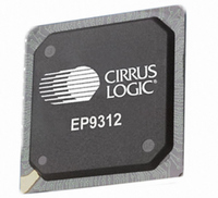
EP9312-IB Cirrus Logic Inc, EP9312-IB Datasheet - Page 243

EP9312-IB
Manufacturer Part Number
EP9312-IB
Description
IC ARM920T MCU 200MHZ 352-PBGA
Manufacturer
Cirrus Logic Inc
Series
EP9r
Datasheets
1.EP9307-CRZ.pdf
(824 pages)
2.EP9312-IBZ.pdf
(4 pages)
3.EP9312-CB.pdf
(62 pages)
4.EP9312-CB.pdf
(17 pages)
Specifications of EP9312-IB
Core Processor
ARM9
Core Size
16/32-Bit
Speed
200MHz
Connectivity
EBI/EMI, EIDE, Ethernet, I²C, IrDA, Keypad/Touchscreen, SPI, UART/USART, USB
Peripherals
AC'97, DMA, I²:S, LCD, LED, MaverickKey, POR, PWM, WDT
Number Of I /o
16
Program Memory Type
ROMless
Ram Size
32K x 8
Voltage - Supply (vcc/vdd)
1.65 V ~ 3.6 V
Data Converters
A/D 8x12b
Oscillator Type
External
Operating Temperature
-40°C ~ 85°C
Package / Case
352-BGA
Processor Series
EP93xx
Core
ARM920T
Data Bus Width
32 bit
3rd Party Development Tools
MDK-ARM, RL-ARM, ULINK2
Lead Free Status / RoHS Status
Contains lead / RoHS non-compliant
Eeprom Size
-
Program Memory Size
-
Lead Free Status / Rohs Status
No
Other names
598-1259
Available stocks
Company
Part Number
Manufacturer
Quantity
Price
Company:
Part Number:
EP9312-IBZ
Manufacturer:
CIRRUS
Quantity:
30
Company:
Part Number:
EP9312-IBZ
Manufacturer:
HITTITE
Quantity:
1 200
- EP9307-CRZ PDF datasheet
- EP9312-IBZ PDF datasheet #2
- EP9312-CB PDF datasheet #3
- EP9312-CB PDF datasheet #4
- Current page: 243 of 824
- Download datasheet (13Mb)
ParllIfIn
DS785UM1
31
15
Address: 0x8003_005C
Default: 0x0000_0000
Definition: Parallel Interface Output/Control Register
Bit Descriptions:
30
14
29
13
28
12
This register, if PIFEN = ‘1’ in the
Smart Panel. A Smart Panel has an integrated controller and frame buffer.
RSVD:
ESTRT:
CNT:
RSVD
RSVD
27
11
26
10
Copyright 2007 Cirrus Logic
25
9
P3 --> D3
P[2:0] --> D[2:0]
SPCLK --> E
Smart Panel R/W and RS signals must be implemented
via GPIOs and controlled via software.
Reserved - Unknown during read
Enable Start - Read/Write
The Enable Signal Start Value for the parallel interface
down counter should be written to this field. When the
parallel interface counter counts down to this value during
a write cycle (see RD bit in the
cycle), the E enable signal on the E pin goes active.
The E enable signal becomes inactive just before the
counter counts down to 0x0, although data remains driven
on the D[7:0] pins throughout the 0x0 count. This allows
data to be driven for one additional clock cycle, providing
data hold time to the Smart Panel.
Count - Read/Write
The counter preload value that is written to this field gets
loaded into the parallel interface down counter. When a
write or read cycle is initiated by writing to the RD bit in the
ParllIfOut
this value.
Raster Engine With Analog/LCD Integrated Timing and Interface
24
8
register, the counter begins to count down from
23
7
VideoAttribs
22
6
ESTRT
21
5
register, is used to access a
20
4
ParllIfOut
DAT
19
3
EP93xx User’s Guide
register for write
18
2
CNT
17
1
16
7-61
0
7
Related parts for EP9312-IB
Image
Part Number
Description
Manufacturer
Datasheet
Request
R

Part Number:
Description:
IC ARM920T MCU 200MHZ 352-PBGA
Manufacturer:
Cirrus Logic Inc
Datasheet:

Part Number:
Description:
IC ARM9 SOC UNIVERSAL 352PBGA
Manufacturer:
Cirrus Logic Inc
Datasheet:

Part Number:
Description:
System-on-Chip Processor
Manufacturer:
Cirrus Logic Inc
Datasheet:

Part Number:
Description:
IC ARM920T MCU 200MHZ 352-PBGA
Manufacturer:
Cirrus Logic Inc
Datasheet:

Part Number:
Description:
IC ARM920T MCU 200MHZ 352-PBGA
Manufacturer:
Cirrus Logic Inc
Datasheet:

Part Number:
Description:
IC ARM920T MCU 166MHZ 208-LQFP
Manufacturer:
Cirrus Logic Inc
Datasheet:

Part Number:
Description:
IC ARM920T MCU 166MHZ 208-LQFP
Manufacturer:
Cirrus Logic Inc
Datasheet:

Part Number:
Description:
Development Kit
Manufacturer:
Cirrus Logic Inc
Datasheet:

Part Number:
Description:
Development Kit
Manufacturer:
Cirrus Logic Inc
Datasheet:

Part Number:
Description:
High-efficiency PFC + Fluorescent Lamp Driver Reference Design
Manufacturer:
Cirrus Logic Inc
Datasheet:

Part Number:
Description:
Development Kit
Manufacturer:
Cirrus Logic Inc
Datasheet:

Part Number:
Description:
Development Kit
Manufacturer:
Cirrus Logic Inc
Datasheet:

Part Number:
Description:
Ref Bd For Speakerbar MSA & DSP Products
Manufacturer:
Cirrus Logic Inc


