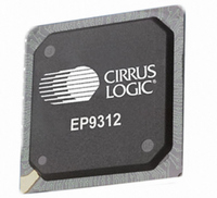
EP9312-IB Cirrus Logic Inc, EP9312-IB Datasheet - Page 18

EP9312-IB
Manufacturer Part Number
EP9312-IB
Description
IC ARM920T MCU 200MHZ 352-PBGA
Manufacturer
Cirrus Logic Inc
Series
EP9r
Datasheets
1.EP9307-CRZ.pdf
(824 pages)
2.EP9312-IBZ.pdf
(4 pages)
3.EP9312-CB.pdf
(62 pages)
4.EP9312-CB.pdf
(17 pages)
Specifications of EP9312-IB
Core Processor
ARM9
Core Size
16/32-Bit
Speed
200MHz
Connectivity
EBI/EMI, EIDE, Ethernet, I²C, IrDA, Keypad/Touchscreen, SPI, UART/USART, USB
Peripherals
AC'97, DMA, I²:S, LCD, LED, MaverickKey, POR, PWM, WDT
Number Of I /o
16
Program Memory Type
ROMless
Ram Size
32K x 8
Voltage - Supply (vcc/vdd)
1.65 V ~ 3.6 V
Data Converters
A/D 8x12b
Oscillator Type
External
Operating Temperature
-40°C ~ 85°C
Package / Case
352-BGA
Processor Series
EP93xx
Core
ARM920T
Data Bus Width
32 bit
3rd Party Development Tools
MDK-ARM, RL-ARM, ULINK2
Lead Free Status / RoHS Status
Contains lead / RoHS non-compliant
Eeprom Size
-
Program Memory Size
-
Lead Free Status / Rohs Status
No
Other names
598-1259
Available stocks
Company
Part Number
Manufacturer
Quantity
Price
Company:
Part Number:
EP9312-IBZ
Manufacturer:
CIRRUS
Quantity:
30
Company:
Part Number:
EP9312-IBZ
Manufacturer:
HITTITE
Quantity:
1 200
- EP9307-CRZ PDF datasheet
- EP9312-IBZ PDF datasheet #2
- EP9312-CB PDF datasheet #3
- EP9312-CB PDF datasheet #4
- Current page: 18 of 824
- Download datasheet (13Mb)
EP93xx User’s Guide
xviii
Table 3-6. LDC/STC Opcode Map ..............................................................................................................3-16
Table 3-7. CDP Opcode Map ......................................................................................................................3-16
Table 3-8. MCR Opcode Map .....................................................................................................................3-17
Table 3-9. MRC Opcode Map .....................................................................................................................3-17
Table 3-10. MaverickCrunch Instruction Set .............................................................................................3-18
Table 3-11. Mnemonic Codes for Loading Floating Point Value from Memory...........................................3-21
Table 3-12. Mnemonic Codes for Loading Integer Value from Memory......................................................3-22
Table 3-13. Mnemonic Codes for Storing Floating Point Values to Memory...............................................3-23
Table 3-14. Mnemonic Codes for Storing Integer Values to Memory .........................................................3-23
Table 4-1. Boot Configuration Options ..........................................................................................................4-5
Table 5-1. Hardware Configuration Control Latched Pins.............................................................................5-2
Table 5-2. Boot Configuration Options ..........................................................................................................5-3
Table 5-3. Clock Speeds and Sources..........................................................................................................5-8
Table 5-4. Peripherals with PCLK Gating....................................................................................................5-10
Table 5-5. Syscon Register List ................................................................................................................5-13
Table 5-6. Priority Order for AHB Arbiter.....................................................................................................5-23
Table 5-7. Audio Interfaces Pin Assignment ...............................................................................................5-26
Table 6-1. Interrupt Configuration .................................................................................................................6-3
Table 6-2. VICx Register Summary...............................................................................................................6-8
Table 7-1. Raster Engine Video Mode Output Examples..............................................................................7-2
Table 7-2. Byte Oriented Frame Buffer Organization....................................................................................7-5
Table 7-3. Output Pixel Transfer Modes .....................................................................................................7-13
Table 7-4. Grayscale Lookup Table (GrySclLUT) .......................................................................................7-17
Table 7-5. Grayscale Timing Diagram.........................................................................................................7-18
Table 7-6. Programming Format .................................................................................................................7-19
Table 7-7. Programming 50% Duty Cycle Into Lookup Table .....................................................................7-22
Table 7-8. Programming 33% Duty Cycle into the Lookup Table ...............................................................7-23
Table 7-9. Programming 33% Duty Cycle into the Lookup Table ...............................................................7-24
Table 7-10. Cursor Memory Organization ...................................................................................................7-25
Table 7-11. Bits P[2:0] in the PixelMode Register.......................................................................................7-32
Table 7-12. Raster Engine Register List .....................................................................................................7-36
Table 7-13. Color Mode Definition Table.....................................................................................................7-58
Table 7-14. Blink Mode Definition Table .....................................................................................................7-58
Table 7-15. Output Shift Mode Table ..........................................................................................................7-59
Table 7-16. Bits per Pixel Scanned Out ......................................................................................................7-59
Table 7-17. Grayscale Look-Up-Table (LUT) ..............................................................................................7-75
Table 8-1. Screen Pixels ...............................................................................................................................8-4
©
Copyright 2007 Cirrus Logic, Inc.
DS785UM1
Related parts for EP9312-IB
Image
Part Number
Description
Manufacturer
Datasheet
Request
R

Part Number:
Description:
IC ARM920T MCU 200MHZ 352-PBGA
Manufacturer:
Cirrus Logic Inc
Datasheet:

Part Number:
Description:
IC ARM9 SOC UNIVERSAL 352PBGA
Manufacturer:
Cirrus Logic Inc
Datasheet:

Part Number:
Description:
System-on-Chip Processor
Manufacturer:
Cirrus Logic Inc
Datasheet:

Part Number:
Description:
IC ARM920T MCU 200MHZ 352-PBGA
Manufacturer:
Cirrus Logic Inc
Datasheet:

Part Number:
Description:
IC ARM920T MCU 200MHZ 352-PBGA
Manufacturer:
Cirrus Logic Inc
Datasheet:

Part Number:
Description:
IC ARM920T MCU 166MHZ 208-LQFP
Manufacturer:
Cirrus Logic Inc
Datasheet:

Part Number:
Description:
IC ARM920T MCU 166MHZ 208-LQFP
Manufacturer:
Cirrus Logic Inc
Datasheet:

Part Number:
Description:
Development Kit
Manufacturer:
Cirrus Logic Inc
Datasheet:

Part Number:
Description:
Development Kit
Manufacturer:
Cirrus Logic Inc
Datasheet:

Part Number:
Description:
High-efficiency PFC + Fluorescent Lamp Driver Reference Design
Manufacturer:
Cirrus Logic Inc
Datasheet:

Part Number:
Description:
Development Kit
Manufacturer:
Cirrus Logic Inc
Datasheet:

Part Number:
Description:
Development Kit
Manufacturer:
Cirrus Logic Inc
Datasheet:

Part Number:
Description:
Ref Bd For Speakerbar MSA & DSP Products
Manufacturer:
Cirrus Logic Inc


