ATSAM3S4CA-CU Atmel, ATSAM3S4CA-CU Datasheet - Page 1063
ATSAM3S4CA-CU
Manufacturer Part Number
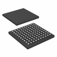
ATSAM3S4CA-CU
Description
IC MCU 32BIT 256KB FLASH 100BGA
Manufacturer
Atmel
Series
SAM3Sr
Specifications of ATSAM3S4CA-CU
Core Processor
ARM® Cortex-M3™
Core Size
32-Bit
Speed
64MHz
Connectivity
EBI/EMI, I²C, MMC, SPI, SSC, UART/USART, USB
Peripherals
Brown-out Detect/Reset, DMA, I²S, POR, PWM, WDT
Number Of I /o
79
Program Memory Size
256KB (256K x 8)
Program Memory Type
FLASH
Ram Size
48K x 8
Voltage - Supply (vcc/vdd)
1.62 V ~ 1.95 V
Data Converters
A/D 16x10/12b, D/A 2x12b
Oscillator Type
Internal
Operating Temperature
-40°C ~ 85°C
Package / Case
100-LFBGA
Processor Series
ATSAM3x
Core
ARM Cortex M3
3rd Party Development Tools
JTRACE-CM3, MDK-ARM, RL-ARM, ULINK2
Development Tools By Supplier
ATSAM3S-EK
Package
100LFBGA
Device Core
ARM Cortex M3
Family Name
AT91
Maximum Speed
64 MHz
Operating Supply Voltage
1.8|3.3 V
Data Bus Width
32 Bit
Number Of Programmable I/os
79
Interface Type
I2C/I2S/SPI/UART/USART/USB
On-chip Adc
16-chx12-bit
On-chip Dac
2-chx12-bit
Number Of Timers
6
Lead Free Status / RoHS Status
Lead free / RoHS Compliant
Eeprom Size
-
Lead Free Status / Rohs Status
Details
Available stocks
Company
Part Number
Manufacturer
Quantity
Price
Company:

Part Number:
ATSAM3S4CA-CU
Manufacturer:
SANYO
Quantity:
1 000


41.7.0.2
6500C–ATARM–8-Feb-11
ADC Application Information
Set TRANSFER = 1 and TRACTIM = 0.
In this case, a timer will trigger the ADC in order to set the correct sampling rate according to the
Track time.
The maximum possible sampling frequency will be defined by t
by the previous formula but with minus 15 × t
Note:
Table 41-35. Analog Inputs
Note:
For more information on data converter terminology, please refer to the application note:
Data Converter Terminology, Atmel lit° 6022.
http://www.atmel.com/dyn/resources/prod_documents/doc6022.pdf
Parameter
Input Voltage Range
Input Leakage Current
Input Capacitance
2. The calculated tracking time (t
• 10 bit mode: 1/f
• 12 bit mode: 1/f
Csample and Ron are taken into account in the formulas
1. Input Voltage range can be up to VDDIN without destruction or over-consumption.
If VDDIO < V
S
S
= t
= t
TRACK
TRACK
ADVREF
- 15 × t
- 15 × t
max input voltage is VDDIO.
CP_ADC
CP_ADC
TRACK
+ 5 t
+ 5 t
) is higher than 15 t
CP_ADC
CP_ADC
CP_ADC
and plus TRANSFER time.
Min
0
SAM3S Preliminary
TRACK
CP_ADC
Typ
in nano seconds, computed
.
V
ADVREF
±0.5
Max
8
Units
µA
pF
1063
Related parts for ATSAM3S4CA-CU
Image
Part Number
Description
Manufacturer
Datasheet
Request
R

Part Number:
Description:
KIT EVAL FOR ATSAM3S4C
Manufacturer:
Atmel
Datasheet:
Part Number:
Description:
Development Boards & Kits - ARM EVAL KIT SAM3S8 & SAM3SD8 series
Manufacturer:
Atmel
Datasheet:

Part Number:
Description:
AT91 ARM Cortex M3-based Processor
Manufacturer:
ATMEL [ATMEL Corporation]
Datasheet:

Part Number:
Description:
DEV KIT FOR AVR/AVR32
Manufacturer:
Atmel
Datasheet:

Part Number:
Description:
INTERVAL AND WIPE/WASH WIPER CONTROL IC WITH DELAY
Manufacturer:
ATMEL Corporation
Datasheet:
Part Number:
Description:
Low-Voltage Voice-Switched IC for Hands-Free Operation
Manufacturer:
ATMEL Corporation
Datasheet:
Part Number:
Description:
MONOLITHIC INTEGRATED FEATUREPHONE CIRCUIT
Manufacturer:
ATMEL Corporation
Datasheet:
Part Number:
Description:
AM-FM Receiver IC U4255BM-M
Manufacturer:
ATMEL Corporation
Datasheet:
Part Number:
Description:
Monolithic Integrated Feature Phone Circuit
Manufacturer:
ATMEL Corporation
Datasheet:
Part Number:
Description:
Multistandard Video-IF and Quasi Parallel Sound Processing
Manufacturer:
ATMEL Corporation
Datasheet:
Part Number:
Description:
High-performance EE PLD
Manufacturer:
ATMEL Corporation
Datasheet:
Part Number:
Description:
8-bit Flash Microcontroller
Manufacturer:
ATMEL Corporation
Datasheet: