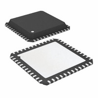
AT32UC3B1256-Z1UR Atmel, AT32UC3B1256-Z1UR Datasheet - Page 591

AT32UC3B1256-Z1UR
Manufacturer Part Number
AT32UC3B1256-Z1UR
Description
MCU AVR32 256K FLASH 48-QFN
Manufacturer
Atmel
Series
AVR®32 UC3r
Datasheet
1.AT32UC3B164-AUR.pdf
(680 pages)
Specifications of AT32UC3B1256-Z1UR
Package / Case
48-QFN Exposed Pad
Voltage - Supply (vcc/vdd)
1.65 V ~ 1.95 V
Operating Temperature
-40°C ~ 85°C
Speed
60MHz
Number Of I /o
28
Core Processor
AVR
Program Memory Type
FLASH
Ram Size
32K x 8
Program Memory Size
256KB (256K x 8)
Data Converters
A/D 6x10b
Oscillator Type
Internal
Peripherals
Brown-out Detect/Reset, DMA, POR, PWM, WDT
Connectivity
I²C, IrDA, SPI, SSC, UART/USART, USB
Core Size
32-Bit
Lead Free Status / RoHS Status
Lead free / RoHS Compliant
Eeprom Size
-
- Current page: 591 of 680
- Download datasheet (10Mb)
27.3.6.1
32059J–12/2010
trace operation
the debug session starts. The AUX port is mapped to two different locations, selectable by OCD
Registers, minimizing the chance that the AUX port will need to be shared with an application.
Debug tools utilizing the AUX port should connect to the device through a Nexus-compliant Mic-
tor-38 connector, as described in the AVR32UC Technical Reference manual. This connector
includes the JTAG signals and the RESET_N pin, giving full access to the programming and
debug features in the device.
Table 27-5.
Figure 27-3. AUX+JTAG based Debugger
Trace features are enabled by writing OCD registers by JTAG. The OCD extracts the trace infor-
mation from the CPU, compresses this information and formats it into variable-length messages
Signal
MCKO
MDO[5:0]
MSEO[1:0]
EVTI_N
EVTO_N
Auxiliary Port Signals
Direction
Output
Output
Output
Output
Input
T r a c e b u f f e r
h i g h s p e e d
Trace data output clock
Trace data output
Trace frame control
Event In
Event Out
Description
A U X
M i c t o r 3 8
A V R 3 2
P C
A U X + J T A G
d e b u g t o o l
J T A G
AT32UC3B
591
Related parts for AT32UC3B1256-Z1UR
Image
Part Number
Description
Manufacturer
Datasheet
Request
R

Part Number:
Description:
DEV KIT FOR AVR/AVR32
Manufacturer:
Atmel
Datasheet:

Part Number:
Description:
INTERVAL AND WIPE/WASH WIPER CONTROL IC WITH DELAY
Manufacturer:
ATMEL Corporation
Datasheet:

Part Number:
Description:
Low-Voltage Voice-Switched IC for Hands-Free Operation
Manufacturer:
ATMEL Corporation
Datasheet:

Part Number:
Description:
MONOLITHIC INTEGRATED FEATUREPHONE CIRCUIT
Manufacturer:
ATMEL Corporation
Datasheet:

Part Number:
Description:
AM-FM Receiver IC U4255BM-M
Manufacturer:
ATMEL Corporation
Datasheet:

Part Number:
Description:
Monolithic Integrated Feature Phone Circuit
Manufacturer:
ATMEL Corporation
Datasheet:

Part Number:
Description:
Multistandard Video-IF and Quasi Parallel Sound Processing
Manufacturer:
ATMEL Corporation
Datasheet:

Part Number:
Description:
High-performance EE PLD
Manufacturer:
ATMEL Corporation
Datasheet:

Part Number:
Description:
8-bit Flash Microcontroller
Manufacturer:
ATMEL Corporation
Datasheet:

Part Number:
Description:
2-Wire Serial EEPROM
Manufacturer:
ATMEL Corporation
Datasheet:


