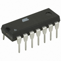
AT89LP214-20PU Atmel, AT89LP214-20PU Datasheet - Page 97

AT89LP214-20PU
Manufacturer Part Number
AT89LP214-20PU
Description
MCU 8051 2K FLASH 20MHZ 14-PDIP
Manufacturer
Atmel
Series
89LPr
Datasheet
1.AT89LP213-20PU.pdf
(98 pages)
Specifications of AT89LP214-20PU
Core Processor
8051
Core Size
8-Bit
Speed
20MHz
Connectivity
SPI, UART/USART
Peripherals
Brown-out Detect/Reset, POR, PWM, WDT
Number Of I /o
12
Program Memory Size
2KB (2K x 8)
Program Memory Type
FLASH
Ram Size
128 x 8
Voltage - Supply (vcc/vdd)
2.4 V ~ 5.5 V
Oscillator Type
Internal
Operating Temperature
-40°C ~ 85°C
Package / Case
14-DIP (0.300", 7.62mm)
Processor Series
AT89x
Core
8051
Data Bus Width
8 bit
Data Ram Size
128 B
Interface Type
SPI/UART
Maximum Clock Frequency
20 MHz
Number Of Programmable I/os
12
Number Of Timers
2
Operating Supply Voltage
2.4 V to 5 V
Maximum Operating Temperature
+ 85 C
Mounting Style
Through Hole
3rd Party Development Tools
PK51, CA51, A51, ULINK2
Development Tools By Supplier
AT89ISP
Minimum Operating Temperature
- 40 C
Lead Free Status / RoHS Status
Lead free / RoHS Compliant
Eeprom Size
-
Data Converters
-
Lead Free Status / Rohs Status
Lead free / RoHS Compliant
Table of Contents (Continued)
3538E–MICRO–11/10
20 Programmable Watchdog Timer ........................................................... 58
21 Instruction Set Summary ...................................................................... 60
22 On-chip Debug System ......................................................................... 64
23 Programming the Flash Memory .......................................................... 65
24 Electrical Characteristics ...................................................................... 77
25 Ordering Information ............................................................................. 90
26 Packaging Information .......................................................................... 91
27 Revision History ..................................................................................... 93
20.1
22.1
22.2
22.3
23.1
23.2
23.3
23.4
23.5
23.6
23.7
23.8
24.1
24.2
24.3
24.4
24.5
24.6
24.7
25.1
26.1
26.2
Software Reset ................................................................................................59
Physical Interface ............................................................................................64
Software Breakpoints ......................................................................................65
Limitations of On-chip Debug ..........................................................................65
Physical Interface ............................................................................................66
Memory Organization ......................................................................................67
Command Format ............................................................................................68
Status Register ................................................................................................71
DATA Polling ...................................................................................................71
Flash Security ..................................................................................................71
User Configuration Fuses ................................................................................72
Programming Interface Timing ........................................................................73
Absolute Maximum Ratings* ...........................................................................77
DC Characteristics ...........................................................................................77
Typical Characteristics ....................................................................................78
Clock Characteristics .......................................................................................84
Serial Peripheral Interface Timing ..................................................................85
Serial Port Timing: Shift Register Mode Test Conditions ................................87
Test Conditions ................................................................................................88
Green Package Option (Pb/Halide-free) ..........................................................90
14P3 – PDIP ....................................................................................................91
14X – TSSOP ..................................................................................................92
AT89LP213/214
iii


