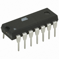
AT89LP214-20PU Atmel, AT89LP214-20PU Datasheet - Page 58

AT89LP214-20PU
Manufacturer Part Number
AT89LP214-20PU
Description
MCU 8051 2K FLASH 20MHZ 14-PDIP
Manufacturer
Atmel
Series
89LPr
Datasheet
1.AT89LP213-20PU.pdf
(98 pages)
Specifications of AT89LP214-20PU
Core Processor
8051
Core Size
8-Bit
Speed
20MHz
Connectivity
SPI, UART/USART
Peripherals
Brown-out Detect/Reset, POR, PWM, WDT
Number Of I /o
12
Program Memory Size
2KB (2K x 8)
Program Memory Type
FLASH
Ram Size
128 x 8
Voltage - Supply (vcc/vdd)
2.4 V ~ 5.5 V
Oscillator Type
Internal
Operating Temperature
-40°C ~ 85°C
Package / Case
14-DIP (0.300", 7.62mm)
Processor Series
AT89x
Core
8051
Data Bus Width
8 bit
Data Ram Size
128 B
Interface Type
SPI/UART
Maximum Clock Frequency
20 MHz
Number Of Programmable I/os
12
Number Of Timers
2
Operating Supply Voltage
2.4 V to 5 V
Maximum Operating Temperature
+ 85 C
Mounting Style
Through Hole
3rd Party Development Tools
PK51, CA51, A51, ULINK2
Development Tools By Supplier
AT89ISP
Minimum Operating Temperature
- 40 C
Lead Free Status / RoHS Status
Lead free / RoHS Compliant
Eeprom Size
-
Data Converters
-
Lead Free Status / Rohs Status
Lead free / RoHS Compliant
20. Programmable Watchdog Timer
58
AT89LP213/214
The programmable Watchdog Timer (WDT) protects the system from incorrect execution by trig-
gering a system reset when it times out after the software has failed to feed the timer prior to the
timer overflow. By Default the WDT counts CPU clock cycles. The prescaler bits, PS0, PS1 and
PS2 in SFR WDTCON are used to set the period of the Watchdog Timer from 16K to 2048K
clock cycles. The Timer Prescaler can also be used to lengthen the time-out period (see
9-2 on page
times out without being serviced, an internal RST pulse is generated to reset the CPU. See
Table 20-1
Table 20-1.
Note:
The Watchdog Timer consists of a 14-bit timer with 7-bit programmable prescaler. Writing the
sequence 1EH/E1H to the WDTRST register enables the timer. When the WDT is enabled, the
WDTEN bit in WDTCON will be set to “1”. To prevent the WDT from generating a reset when if
overflows, the watchdog feed sequence must be written to WDTRST before the end of the time-
out period. To feed the watchdog, two write instructions must be sequentially executed success-
fully. Between the two write instructions, SFR reads are allowed, but writes are not allowed. The
instructions should move 1EH to the WDTRST register and then 1EH to the WDTRST register.
An incorrect feed or enable sequence will cause an immediate watchdog reset. The program
sequence to feed or enable the watchdog timer is as follows:
PS2
1. The WDT time-out period is dependent on the system clock frequency.
0
0
0
0
1
1
1
1
for the available WDT period selections.
14) The WDT is disabled by Reset and during Power-down mode. When the WDT
MOV WDTRST, #01Eh
MOV WDTRST, #0E1h
Watchdog Timer Time-out Period Selection
WDT Prescaler Bits
Time-out Period
PS1
0
0
1
1
0
0
1
1
=
------------------------------------------------------ -
Oscillator Frequency
2
PS0
(
0
1
0
1
0
1
0
1
PS
+
14
)
×
(
TPS
+
(Clock Cycles)
1
)
Period
1024K
2048K
128K
256K
512K
16K
32K
64K
(1)
3538E–MICRO–11/10
Table


