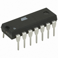
AT89LP214-20PU Atmel, AT89LP214-20PU Datasheet - Page 95

AT89LP214-20PU
Manufacturer Part Number
AT89LP214-20PU
Description
MCU 8051 2K FLASH 20MHZ 14-PDIP
Manufacturer
Atmel
Series
89LPr
Datasheet
1.AT89LP213-20PU.pdf
(98 pages)
Specifications of AT89LP214-20PU
Core Processor
8051
Core Size
8-Bit
Speed
20MHz
Connectivity
SPI, UART/USART
Peripherals
Brown-out Detect/Reset, POR, PWM, WDT
Number Of I /o
12
Program Memory Size
2KB (2K x 8)
Program Memory Type
FLASH
Ram Size
128 x 8
Voltage - Supply (vcc/vdd)
2.4 V ~ 5.5 V
Oscillator Type
Internal
Operating Temperature
-40°C ~ 85°C
Package / Case
14-DIP (0.300", 7.62mm)
Processor Series
AT89x
Core
8051
Data Bus Width
8 bit
Data Ram Size
128 B
Interface Type
SPI/UART
Maximum Clock Frequency
20 MHz
Number Of Programmable I/os
12
Number Of Timers
2
Operating Supply Voltage
2.4 V to 5 V
Maximum Operating Temperature
+ 85 C
Mounting Style
Through Hole
3rd Party Development Tools
PK51, CA51, A51, ULINK2
Development Tools By Supplier
AT89ISP
Minimum Operating Temperature
- 40 C
Lead Free Status / RoHS Status
Lead free / RoHS Compliant
Eeprom Size
-
Data Converters
-
Lead Free Status / Rohs Status
Lead free / RoHS Compliant
Table of Contents
3538E–MICRO–11/10
1
2
3
4
5
6
7
8
9
10 Reset ....................................................................................................... 14
Features ..................................................................................................... 1
Description ............................................................................................... 1
Pin Configuration ..................................................................................... 2
Pin Description ......................................................................................... 3
Block Diagram .......................................................................................... 5
Comparison to Standard 8051 ................................................................ 6
Memory Organization .............................................................................. 7
Special Function Registers ..................................................................... 9
Enhanced CPU ....................................................................................... 10
System Clock ......................................................................................... 12
2.1
2.2
5.1
5.2
5.3
5.4
5.5
5.6
5.7
5.8
6.1
6.2
8.1
9.1
9.2
9.3
9.4
10.1
10.2
10.3
10.4
AT89LP213: 14-lead TSSOP/PDIP ...................................................................2
AT89LP214: 14-lead TSSOP/PDIP ...................................................................2
System Clock .....................................................................................................6
Instruction Execution with Single-cycle Fetch ...................................................6
Interrupt Handling ..............................................................................................6
Timer/Counters ..................................................................................................6
Serial Port ..........................................................................................................6
Watchdog Timer ................................................................................................7
I/O Ports ............................................................................................................7
Reset .................................................................................................................7
Program Memory ...............................................................................................7
Data Memory .....................................................................................................8
Restrictions on Certain Instructions .................................................................11
Crystal Oscillator .............................................................................................12
External Clock Source .....................................................................................13
Internal RC Oscillator ......................................................................................13
System Clock Out ............................................................................................13
Power-on Reset ...............................................................................................14
Brown-out Reset ..............................................................................................16
External Reset .................................................................................................16
Watchdog Reset ..............................................................................................17
AT89LP213/214
i


