Z8F083ASJ020EG Zilog, Z8F083ASJ020EG Datasheet - Page 154
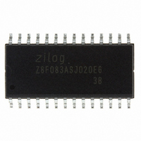
Z8F083ASJ020EG
Manufacturer Part Number
Z8F083ASJ020EG
Description
IC ENCORE XP MCU FLASH 8K 28SOIC
Manufacturer
Zilog
Series
Encore!®r
Datasheet
1.Z8F083ASJ020EG.pdf
(256 pages)
Specifications of Z8F083ASJ020EG
Core Processor
Z8
Core Size
8-Bit
Speed
20MHz
Peripherals
Brown-out Detect/Reset, LED, POR, PWM, WDT
Number Of I /o
23
Program Memory Size
8KB (8K x 8)
Program Memory Type
FLASH
Ram Size
256 x 8
Voltage - Supply (vcc/vdd)
2.7 V ~ 3.6 V
Data Converters
A/D 8x10b
Oscillator Type
Internal
Operating Temperature
-40°C ~ 105°C
Package / Case
28-SOIC (7.5mm Width)
Data Bus Width
8 bit
Data Ram Size
256 B
Maximum Clock Frequency
20 MHz
Number Of Programmable I/os
23
Number Of Timers
2
Maximum Operating Temperature
+ 105 C
Mounting Style
SMD/SMT
Minimum Operating Temperature
- 40 C
On-chip Adc
10 bit, 8 Channel
For Use With
770-1002 - ISP 4PORT ZILOG Z8 ENCORE! MCU269-4672 - KIT DEVELOPMENT F083A
Lead Free Status / RoHS Status
Lead free / RoHS Compliant
Eeprom Size
-
Connectivity
-
Lead Free Status / Rohs Status
Details
Other names
269-4558-5
Available stocks
Company
Part Number
Manufacturer
Quantity
Price
Company:

Part Number:
Z8F083ASJ020EG
Manufacturer:
Zilog
Quantity:
363


On-Chip Debugger Control Register Definitions
PS026308-1207
OCD Control Register
•
•
•
The OCD control register controls the state of the On-Chip Debugger. This register is used
to enter or exit DEBUG mode and to enable the
Z8 Encore! F083A Series device.
A reset and stop function is achieved by writing
function is achieved by writing
function is implemented by writing
program memory size and is approximately equal to the system clock period multiplied by
the number of bytes in the program memory.
DBG
DBG
DBG
Step Instruction (10H)—The step instruction command, steps one assembly instruction
at the current program counter (PC) location. If the device is not in DEBUG mode or the
Flash read protect option bit is enabled, the OCD ignores this command.
DBG
Stuff Instruction (11H)—The stuff instruction command, steps one assembly instruction
and allows specification of the first byte of the instruction. The remaining 0-4 bytes of the
instruction are read from program memory. This command is useful for stepping over
instructions where the first byte of the instruction has been overwritten by a breakpoint. If
the device is not in DEBUG mode or the Flash read protect option bit is enabled, the OCD
ignores this command.
DBG
DBG
Execute Instruction (12H)—The execute instruction command allows sending an entire
instruction to be executed to the eZ8 CPU. This command also steps over breakpoints. The
number of bytes to send for the instruction depends on the Opcode. If the device is not in
DEBUG mode or the Flash read protect option bit is enabled, this command reads and
discards one byte.
DBG
DBG
0EH
CRC[15:8]
CRC[7:0]
10H
11H
opcode[7:0]
12H
1-5 byte opcode
41H
to this register. If the device is in DEBUG mode, a run
40H
to this register.
BRK
81H
instruction. It also resets the
to this register. A reset and
Z8 Encore!
Product Specification
®
On-Chip Debugger
F083A Series
G
o
142
Related parts for Z8F083ASJ020EG
Image
Part Number
Description
Manufacturer
Datasheet
Request
R

Part Number:
Description:
Communication Controllers, ZILOG INTELLIGENT PERIPHERAL CONTROLLER (ZIP)
Manufacturer:
Zilog, Inc.
Datasheet:

Part Number:
Description:
KIT DEV FOR Z8 ENCORE 16K TO 64K
Manufacturer:
Zilog
Datasheet:

Part Number:
Description:
KIT DEV Z8 ENCORE XP 28-PIN
Manufacturer:
Zilog
Datasheet:

Part Number:
Description:
DEV KIT FOR Z8 ENCORE 8K/4K
Manufacturer:
Zilog
Datasheet:

Part Number:
Description:
KIT DEV Z8 ENCORE XP 28-PIN
Manufacturer:
Zilog
Datasheet:

Part Number:
Description:
DEV KIT FOR Z8 ENCORE 4K TO 8K
Manufacturer:
Zilog
Datasheet:
Part Number:
Description:
CMOS Z8 microcontroller. ROM 16 Kbytes, RAM 256 bytes, speed 16 MHz, 32 lines I/O, 3.0V to 5.5V
Manufacturer:
Zilog, Inc.
Datasheet:
Part Number:
Description:
Low-cost microcontroller. 512 bytes ROM, 61 bytes RAM, 8 MHz
Manufacturer:
Zilog, Inc.
Datasheet:
Part Number:
Description:
Z8 4K OTP Microcontroller
Manufacturer:
Zilog, Inc.
Datasheet:
Part Number:
Description:
CMOS SUPER8 ROMLESS MCU
Manufacturer:
Zilog, Inc.
Datasheet:
Part Number:
Description:
SL1866 CMOSZ8 OTP Microcontroller
Manufacturer:
Zilog, Inc.
Datasheet:
Part Number:
Description:
SL1866 CMOSZ8 OTP Microcontroller
Manufacturer:
Zilog, Inc.
Datasheet:
Part Number:
Description:
OTP (KB) = 1, RAM = 125, Speed = 12, I/O = 14, 8-bit Timers = 2, Comm Interfaces Other Features = Por, LV Protect, Voltage = 4.5-5.5V
Manufacturer:
Zilog, Inc.
Datasheet:
Part Number:
Description:
Manufacturer:
Zilog, Inc.
Datasheet: