HD64F3687GFPV Renesas Electronics America, HD64F3687GFPV Datasheet - Page 264
HD64F3687GFPV
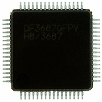
Manufacturer Part Number
HD64F3687GFPV
Description
IC H8 MCU FLASH 56K 64LQFP
Manufacturer
Renesas Electronics America
Series
H8® H8/300H Tinyr
Specifications of HD64F3687GFPV
Core Processor
H8/300H
Core Size
16-Bit
Speed
20MHz
Connectivity
I²C, SCI
Peripherals
LVD, POR, PWM, WDT
Number Of I /o
45
Program Memory Size
56KB (56K x 8)
Program Memory Type
FLASH
Ram Size
4K x 8
Voltage - Supply (vcc/vdd)
3 V ~ 5.5 V
Data Converters
A/D 8x10b
Oscillator Type
Internal
Operating Temperature
-20°C ~ 75°C
Package / Case
64-LQFP
Package
64LQFP
Family Name
H8
Maximum Speed
20 MHz
Operating Supply Voltage
3.3|5 V
Data Bus Width
16|32 Bit
Number Of Programmable I/os
45
Interface Type
I2C/SCI
On-chip Adc
8-chx10-bit
Number Of Timers
3
For Use With
R0K436079S000BE - KIT DEV FOR H8/36079 W/COMPILER
Lead Free Status / RoHS Status
Lead free / RoHS Compliant
Eeprom Size
-
Available stocks
Company
Part Number
Manufacturer
Quantity
Price
Company:

Part Number:
HD64F3687GFPV
Manufacturer:
Renesas Electronics America
Quantity:
10 000


Section 3 Processing States
3.3.2
Exception-Handling Sequences
Reset Exception Handling: Reset exception handling has the highest priority. The reset state is
entered when the RES signal goes low. Then, if RES goes high again, reset exception handling
starts when the reset condition is satisfied. Refer to the relevant microcontroller hardware manual
for details about the reset condition. When reset exception handling starts the CPU fetches a start
address from the exception vector table and starts program execution from that address. All
interrupts, including NMI, are disabled during the reset exception-handling sequence and
immediately after it ends.
Interrupt Exception Handling and Trap Instruction Exception Handling: When these exception-
handling sequences begin, the CPU references the stack pointer (ER7) and pushes the program
counter and condition-code register on the stack. Next, if the UE bit in the system control register
(SYSCR) is set to 1, the CPU sets the I bit in the condition-code register to 1. If the UE bit is
cleared to 0, the CPU sets both the I bit and the UI bit in the condition-code register to 1. Then the
CPU fetches a start address from the exception vector table and execution branches to that
address.
The program-counter value pushed on the stack and the start address fetched from the vector table
are 16 bits long in normal mode and 24 bits long in advanced mode. Figure 3.4 shows the stack
after the exception-handling sequence.
Rev. 3.00 Dec 13, 2004 page 248 of 258
REJ09B0213-0300
Related parts for HD64F3687GFPV
Image
Part Number
Description
Manufacturer
Datasheet
Request
R


Part Number:
Description:
KIT STARTER FOR M16C/29
Manufacturer:
Renesas Electronics America
Datasheet:

Part Number:
Description:
KIT STARTER FOR R8C/2D
Manufacturer:
Renesas Electronics America
Datasheet:

Part Number:
Description:
R0K33062P STARTER KIT
Manufacturer:
Renesas Electronics America
Datasheet:

Part Number:
Description:
KIT STARTER FOR R8C/23 E8A
Manufacturer:
Renesas Electronics America
Datasheet:

Part Number:
Description:
KIT STARTER FOR R8C/25
Manufacturer:
Renesas Electronics America
Datasheet:

Part Number:
Description:
KIT STARTER H8S2456 SHARPE DSPLY
Manufacturer:
Renesas Electronics America
Datasheet:

Part Number:
Description:
KIT STARTER FOR R8C38C
Manufacturer:
Renesas Electronics America
Datasheet:

Part Number:
Description:
KIT STARTER FOR R8C35C
Manufacturer:
Renesas Electronics America
Datasheet:

Part Number:
Description:
KIT STARTER FOR R8CL3AC+LCD APPS
Manufacturer:
Renesas Electronics America
Datasheet:
Part Number:
Description:
KIT STARTER FOR RX610
Manufacturer:
Renesas Electronics America
Datasheet:

Part Number:
Description:
KIT STARTER FOR R32C/118
Manufacturer:
Renesas Electronics America
Datasheet:

Part Number:
Description:
KIT DEV RSK-R8C/26-29
Manufacturer:
Renesas Electronics America
Datasheet:

Part Number:
Description:
KIT STARTER FOR SH7124
Manufacturer:
Renesas Electronics America
Datasheet:

Part Number:
Description:
KIT STARTER FOR H8SX/1622
Manufacturer:
Renesas Electronics America
Datasheet: