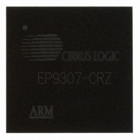
EP9307-CRZ Cirrus Logic Inc, EP9307-CRZ Datasheet - Page 15

EP9307-CRZ
Manufacturer Part Number
EP9307-CRZ
Description
IC ARM9 SOC ARM920T 272TFBGA
Manufacturer
Cirrus Logic Inc
Series
EP9r
Datasheets
1.EP9307-CRZ.pdf
(16 pages)
2.EP9307-CRZ.pdf
(50 pages)
3.EP9307-CRZ.pdf
(824 pages)
4.EP9307-CRZ.pdf
(48 pages)
Specifications of EP9307-CRZ
Core Size
16/32-Bit
Core Processor
ARM9
Speed
200MHz
Connectivity
EBI/EMI, Ethernet, I²C, IrDA, Keypad/Touchscreen, SPI, UART/USART, USB
Peripherals
AC'97, DMA, I²:S, LCD, LED, MaverickKey, POR, PWM, WDT
Number Of I /o
14
Program Memory Type
ROMless
Ram Size
32K x 8
Voltage - Supply (vcc/vdd)
1.65 V ~ 3.6 V
Data Converters
A/D 8x12b
Oscillator Type
External
Operating Temperature
0°C ~ 70°C
Package / Case
272-TFBGA
Controller Family/series
(ARM9)
No. Of I/o's
14
Ram Memory Size
32MB
Cpu Speed
200MHz
No. Of Timers
4
No. Of Pwm Channels
1
Digital Ic Case Style
TFBGA
Embedded Interface Type
AC97, I2S, SPI, UART, USB
Rohs Compliant
Yes
Processor Series
EP93xx
Core
ARM920T
Data Bus Width
32 bit
3rd Party Development Tools
MDK-ARM, RL-ARM, ULINK2
Development Tools By Supplier
EDB9307A-Z
Lead Free Status / RoHS Status
Lead free / RoHS Compliant
For Use With
598-1133 - KIT DEVELOPMENT EP9307 ARM9
Eeprom Size
-
Program Memory Size
-
Lead Free Status / Rohs Status
Details
Other names
598-1138
Available stocks
Company
Part Number
Manufacturer
Quantity
Price
Part Number:
EP9307-CRZ
Manufacturer:
CIRRUS
Quantity:
20 000
Part Number:
EP9307-CRZ/E2
Manufacturer:
CIRRUS
Quantity:
20 000
Company:
Part Number:
EP9307-CRZR
Manufacturer:
Cirrus Logic Inc
Quantity:
10 000
- EP9307-CRZ PDF datasheet
- EP9307-CRZ PDF datasheet #2
- EP9307-CRZ PDF datasheet #3
- EP9307-CRZ PDF datasheet #4
- Current page: 15 of 824
- Download datasheet (13Mb)
EP93xx User’s Guide
Figure 4-1. Flow Chart of Boot ROM Software..............................................................................................4-4
Figure 4-2. Flow chart of Boot Sequence for 16-bit SDRAM Devices ...........................................................4-7
Figure 5-1. Phase Locked Loop (PLL) Structure ...........................................................................................5-4
Figure 5-2. Clock Generation System ...........................................................................................................5-6
Figure 5-3. Bus Clock Generation .................................................................................................................5-7
Figure 5-4. Power States and Transitions ...................................................................................................5-11
Figure 6-1. Vectored Interrupt Controller Block Diagram ..............................................................................6-2
Figure 7-1. Raster Engine Block Diagram .....................................................................................................7-8
Figure 7-2. Video Buffer Diagram..................................................................................................................7-9
Figure 7-3. Graphics Matrix for 50% Duty Cycle .........................................................................................7-20
Figure 7-4. Sample Matrix Causing Flickering ............................................................................................7-21
Figure 7-5.. Sample Matrix That Avoids Flickering......................................................................................7-21
Figure 7-6. Programming for One-third Luminous Intensity ........................................................................7-22
Figure 7-7. Creating Bit Patterns that Move to the Right.............................................................................7-23
Figure 7-8. Three and Four Count Axis .......................................................................................................7-24
Figure 7-9. Progressive/Dual Scan Video Signals ......................................................................................7-29
Figure 7-10. Interlaced Video Signals .........................................................................................................7-30
Figure 9-1. 1/10/100 Mbps Ethernet LAN Controller Block Diagram.............................................................9-1
Figure 9-2. Ethernet Frame / Packet Format (Type II only)...........................................................................9-4
Figure 9-3. Packet Transmission Process.....................................................................................................9-5
Figure 9-4. Carrier Deference State Diagram ...............................................................................................9-6
Figure 9-5. Data Bit Transmission Order.......................................................................................................9-8
Figure 9-6. CRC Logic...................................................................................................................................9-9
Figure 9-7. Receive Descriptor Format and Data Fragments .....................................................................9-14
Figure 9-8. Receive Status Queue ..............................................................................................................9-17
Figure 9-9. Receive Flow Diagram ............................................................................................................9-21
Figure 9-10. Receive Descriptor Data/Status Flow .....................................................................................9-23
Figure 9-11. Receive Descriptor Example...................................................................................................9-24
Figure 9-12. Receive Frame Pre-processing ..............................................................................................9-25
Figure 9-13. Transmit Descriptor Format and Data Fragments ..................................................................9-27
Figure 9-14. Multiple Fragments Per Transmit Frame ................................................................................9-28
Figure 9-15. Transmit Status Queue ...........................................................................................................9-31
Figure 9-16. Transmit Flow Diagram ...........................................................................................................9-34
Figure 9-17. Transmit Descriptor Data/Status Flow ....................................................................................9-36
Figure 10-1. DMA M2P/P2M Finite State Machine .....................................................................................10-7
Figure 10-2. M2M DMA Control Finite State Machine...............................................................................10-10
Figure 10-3. M2M DMA Buffer Finite State Machine.................................................................................10-12
©
DS785UM1
Copyright 2007 Cirrus Logic, Inc.
xv
Related parts for EP9307-CRZ
Image
Part Number
Description
Manufacturer
Datasheet
Request
R

Part Number:
Description:
IC ARM9 SOC ARM920T 272TFBGA
Manufacturer:
Cirrus Logic Inc
Datasheet:

Part Number:
Description:
IC Universal Platform ARM9 SOC Prcessor
Manufacturer:
Cirrus Logic Inc
Datasheet:

Part Number:
Description:
IC Universal Platform ARM9 SOC Prcessor
Manufacturer:
Cirrus Logic Inc

Part Number:
Description:
IC,MICROPROCESSOR,32-BIT,CMOS,BGA,272PIN,PLASTIC
Manufacturer:
Cirrus Logic Inc
Datasheet:

Part Number:
Description:
IC Universal Platform ARM9 SOC Prcessor
Manufacturer:
Cirrus Logic Inc
Datasheet:

Part Number:
Description:
Microcontrollers (MCU) IC Universal Platfrm ARM9 SOC Prcessor
Manufacturer:
Cirrus Logic Inc

Part Number:
Description:
Microcontrollers (MCU) IC Universal Platfrm ARM9 SOC Prcessor
Manufacturer:
Cirrus Logic Inc

Part Number:
Description:
MCU, MPU & DSP Development Tools Eval Bd Uni. ARM9 SOC Processor
Manufacturer:
Cirrus Logic Inc
Datasheet:

Part Number:
Description:
Development Kit
Manufacturer:
Cirrus Logic Inc
Datasheet:

Part Number:
Description:
Development Kit
Manufacturer:
Cirrus Logic Inc
Datasheet:

Part Number:
Description:
High-efficiency PFC + Fluorescent Lamp Driver Reference Design
Manufacturer:
Cirrus Logic Inc
Datasheet:

Part Number:
Description:
Development Kit
Manufacturer:
Cirrus Logic Inc
Datasheet:

Part Number:
Description:
Ref Bd For Speakerbar MSA & DSP Products
Manufacturer:
Cirrus Logic Inc


