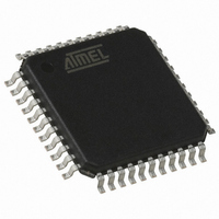
AT89C51ID2-RLTUM Atmel, AT89C51ID2-RLTUM Datasheet - Page 87

AT89C51ID2-RLTUM
Manufacturer Part Number
AT89C51ID2-RLTUM
Description
IC 8051 MCU FLASH 64K 44VQFP
Manufacturer
Atmel
Series
89Cr
Datasheet
1.AT89C51ID2-RLTUM.pdf
(157 pages)
Specifications of AT89C51ID2-RLTUM
Core Processor
8051
Core Size
8-Bit
Speed
60MHz
Connectivity
I²C, SPI, UART/USART
Peripherals
POR, PWM, WDT
Number Of I /o
34
Program Memory Size
64KB (64K x 8)
Program Memory Type
FLASH
Eeprom Size
2K x 8
Ram Size
2K x 8
Voltage - Supply (vcc/vdd)
2.7 V ~ 5.5 V
Oscillator Type
External
Operating Temperature
-40°C ~ 85°C
Package / Case
44-TQFP, 44-VQFP
Processor Series
AT89x
Core
8051
Data Bus Width
8 bit
Data Ram Size
2 KB
Interface Type
UART, SPI, TWI
Maximum Clock Frequency
60 MHz
Number Of Programmable I/os
34
Number Of Timers
3
Operating Supply Voltage
2.7 V to 5.5 V
Maximum Operating Temperature
+ 85 C
Mounting Style
SMD/SMT
3rd Party Development Tools
PK51, CA51, A51, ULINK2
Minimum Operating Temperature
- 40 C
Package
44VQFP
Device Core
8051
Family Name
89C
Maximum Speed
40 MHz
Height
1.45 mm
Length
10.1 mm
Supply Voltage (max)
5.5 V
Supply Voltage (min)
2.7 V
Width
10.1 mm
For Use With
AT89OCD-01 - USB EMULATOR FOR AT8XC51 MCU
Lead Free Status / RoHS Status
Lead free / RoHS Compliant
Data Converters
-
Lead Free Status / Rohs Status
Details
Available stocks
Company
Part Number
Manufacturer
Quantity
Price
Company:
Part Number:
AT89C51ID2-RLTUM
Manufacturer:
ATMEL
Quantity:
13 937
Table 66. Status in Master Transmitter Mode
87
SSSTA
Status
Code
08h
10h
18h
20h
28h
30h
38h
Status of the Two-
wire Bus and Two-
wire Hardware
A START condition has
been transmitted
A repeated START
condition has been
transmitted
SLA+W has been
transmitted; ACK has
been received
SLA+W has been
transmitted; NOT ACK
has been received
Data byte has been
transmitted; ACK has
been received
Data byte has been
transmitted; NOT ACK
has been received
Arbitration lost in
SLA+W or data bytes
AT89C51ID2
To/From SSDAT
Write SLA+W
Write SLA+W
Write SLA+R
Write data byte
No SSDAT action
No SSDAT action
No SSDAT action
Write data byte
No SSDAT action
No SSDAT action
No SSDAT action
Write data byte
No SSDAT action
No SSDAT action
No SSDAT action
Write data byte
No SSDAT action
No SSDAT action
No SSDAT action
No SSDAT action
No SSDAT action
Application software response
SSSTA
X
X
X
0
1
0
1
0
1
0
1
0
1
0
1
0
1
0
1
0
1
SSSTO
To SSCON
0
0
0
0
0
1
1
0
0
1
1
0
0
1
1
0
0
1
1
0
0
SSI
0
0
0
0
0
0
0
0
0
0
0
0
0
0
0
0
0
0
0
0
0
SSAA
X
X
X
X
X
X
X
X
X
X
X
X
X
X
X
X
X
X
X
X
X
Next Action Taken by Two-wire Hardware
SLA+W will be transmitted.
SLA+W will be transmitted.
SLA+R will be transmitted.
Logic will switch to master receiver mode
Data byte will be transmitted.
Repeated START will be transmitted.
STOP condition will be transmitted and SSSTO flag
will be reset.
STOP condition followed by a START condition will
be transmitted and SSSTO flag will be reset.
Data byte will be transmitted.
Repeated START will be transmitted.
STOP condition will be transmitted and SSSTO flag
will be reset.
STOP condition followed by a START condition will
be transmitted and SSSTO flag will be reset.
Data byte will be transmitted.
Repeated START will be transmitted.
STOP condition will be transmitted and SSSTO flag
will be reset.
STOP condition followed by a START condition will
be transmitted and SSSTO flag will be reset.
Data byte will be transmitted.
Repeated START will be transmitted.
STOP condition will be transmitted and SSSTO flag
will be reset.
STOP condition followed by a START condition will
be transmitted and SSSTO flag will be reset.
Two-wire bus will be released and not addressed
slave mode will be entered.
A START condition will be transmitted when the bus
becomes free.
4289C–8051–11/05


