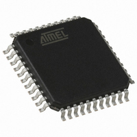
AT89C51ID2-RLTUM Atmel, AT89C51ID2-RLTUM Datasheet - Page 18

AT89C51ID2-RLTUM
Manufacturer Part Number
AT89C51ID2-RLTUM
Description
IC 8051 MCU FLASH 64K 44VQFP
Manufacturer
Atmel
Series
89Cr
Datasheet
1.AT89C51ID2-RLTUM.pdf
(157 pages)
Specifications of AT89C51ID2-RLTUM
Core Processor
8051
Core Size
8-Bit
Speed
60MHz
Connectivity
I²C, SPI, UART/USART
Peripherals
POR, PWM, WDT
Number Of I /o
34
Program Memory Size
64KB (64K x 8)
Program Memory Type
FLASH
Eeprom Size
2K x 8
Ram Size
2K x 8
Voltage - Supply (vcc/vdd)
2.7 V ~ 5.5 V
Oscillator Type
External
Operating Temperature
-40°C ~ 85°C
Package / Case
44-TQFP, 44-VQFP
Processor Series
AT89x
Core
8051
Data Bus Width
8 bit
Data Ram Size
2 KB
Interface Type
UART, SPI, TWI
Maximum Clock Frequency
60 MHz
Number Of Programmable I/os
34
Number Of Timers
3
Operating Supply Voltage
2.7 V to 5.5 V
Maximum Operating Temperature
+ 85 C
Mounting Style
SMD/SMT
3rd Party Development Tools
PK51, CA51, A51, ULINK2
Minimum Operating Temperature
- 40 C
Package
44VQFP
Device Core
8051
Family Name
89C
Maximum Speed
40 MHz
Height
1.45 mm
Length
10.1 mm
Supply Voltage (max)
5.5 V
Supply Voltage (min)
2.7 V
Width
10.1 mm
For Use With
AT89OCD-01 - USB EMULATOR FOR AT8XC51 MCU
Lead Free Status / RoHS Status
Lead free / RoHS Compliant
Data Converters
-
Lead Free Status / Rohs Status
Details
Available stocks
Company
Part Number
Manufacturer
Quantity
Price
Company:
Part Number:
AT89C51ID2-RLTUM
Manufacturer:
ATMEL
Quantity:
13 937
Idle Modes
Power Down Modes
4289C–8051–11/05
•
•
•
•
•
•
•
•
•
•
•
•
•
•
•
Table 20. Overview
PCON.1 PCON.0
X
X
X
0
0
0
0
0
IDLE modes are achieved by using any instruction that writes into PCON.0 bit (IDL)
IDLE modes A and B depend on previous software sequence, prior to writing into
PCON.0 bit:
IDLE MODE A: OscA is running (OscAEn = 1) and selected (CKS = 1)
IDLE MODE B: OscB is running (OscBEn = 1) and selected (CKS = 0)
The unused oscillator OscA or OscB can be stopped by software by clearing
OscAEn or OscBEn respectively.
IDLE mode can be canceled either by Reset, or by activation of any enabled
interruption
In both cases, PCON.0 bit (IDL) is cleared by hardware
Exit from IDLE modes will leave Oscillators control bits (OscEnA, OscEnB, CKS)
unchanged.
POWER DOWN modes are achieved by using any instruction that writes into
PCON.1 bit (PD)
POWER DOWN modes A and B depend on previous software sequence, prior to
writing into PCON.1 bit:
Both OscA and OscB will be stopped.
POWER DOWN mode can be cancelled either by a hardware Reset, an external
interruption, or the keyboard interrupt.
By Reset signal: The CPU will restart according to OSC bit in Hardware Security Bit
(HSB) register.
By INT0 or INT1 interruption, if enabled: (standard behavioral), request on Pads
must be driven low enough to ensure correct restart of the oscillator which was
selected when entering in Power down.
By keyboard Interrupt if enabled: a hardware clear of the PCON.1 flag ensure the
restart of the oscillator which was selected when entering in Power down.
X
X
X
0
0
0
0
1
OscBEn OscAEn
0
1
1
1
0
X
0
X
X
1
1
0
1
0
0
1
CKS
X
1
1
0
0
1
0
1
NORMAL MODE
A, OscB stopped
NORMAL MODE
A, OscB running
NORMAL MODE
B, OscA stopped
NORMAL MODE
B, OscA running
INVALID
INVALID
INVALID
IDLE MODE A
Selected Mode
Default mode after power-up or
Warm Reset
Default mode after power-up or
Warm Reset + OscB running
OscB running and selected
OscB running and selected +
OscA running
OscA & OscB cannot be stopped
at the same time
OscA must not be stopped, as
used for CPU and peripherals
OscB must not be stopped as
used for CPU and peripherals
The CPU is off, OscA supplies the
peripherals, OscB can be disabled
(OscBEn = 0)
AT89C51ID2
Comment
18


