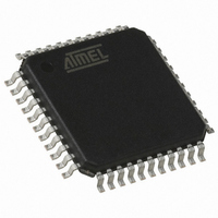
AT89C51ID2-RLTUM Atmel, AT89C51ID2-RLTUM Datasheet - Page 123

AT89C51ID2-RLTUM
Manufacturer Part Number
AT89C51ID2-RLTUM
Description
IC 8051 MCU FLASH 64K 44VQFP
Manufacturer
Atmel
Series
89Cr
Datasheet
1.AT89C51ID2-RLTUM.pdf
(157 pages)
Specifications of AT89C51ID2-RLTUM
Core Processor
8051
Core Size
8-Bit
Speed
60MHz
Connectivity
I²C, SPI, UART/USART
Peripherals
POR, PWM, WDT
Number Of I /o
34
Program Memory Size
64KB (64K x 8)
Program Memory Type
FLASH
Eeprom Size
2K x 8
Ram Size
2K x 8
Voltage - Supply (vcc/vdd)
2.7 V ~ 5.5 V
Oscillator Type
External
Operating Temperature
-40°C ~ 85°C
Package / Case
44-TQFP, 44-VQFP
Processor Series
AT89x
Core
8051
Data Bus Width
8 bit
Data Ram Size
2 KB
Interface Type
UART, SPI, TWI
Maximum Clock Frequency
60 MHz
Number Of Programmable I/os
34
Number Of Timers
3
Operating Supply Voltage
2.7 V to 5.5 V
Maximum Operating Temperature
+ 85 C
Mounting Style
SMD/SMT
3rd Party Development Tools
PK51, CA51, A51, ULINK2
Minimum Operating Temperature
- 40 C
Package
44VQFP
Device Core
8051
Family Name
89C
Maximum Speed
40 MHz
Height
1.45 mm
Length
10.1 mm
Supply Voltage (max)
5.5 V
Supply Voltage (min)
2.7 V
Width
10.1 mm
For Use With
AT89OCD-01 - USB EMULATOR FOR AT8XC51 MCU
Lead Free Status / RoHS Status
Lead free / RoHS Compliant
Data Converters
-
Lead Free Status / Rohs Status
Details
Available stocks
Company
Part Number
Manufacturer
Quantity
Price
Company:
Part Number:
AT89C51ID2-RLTUM
Manufacturer:
ATMEL
Quantity:
13 937
Bootloader Functionality
Introduction
Figure 48. Hardware conditions typical sequence during power-on.
123
AT89C51ID2
The bootloader can be activated by two means: Hardware conditions or regular boot
process.
The Hardware conditions (EA = 1, PSEN = 0) during the Reset# falling edge force the
on-chip bootloader execution. This allows an application to be built that will normally
execute the end user’s code but can be manually forced into default ISP operation.
As PSEN is a an output port in normal operating mode after reset, user application
should take care to release PSEN after falling edge of reset signal. The hardware condi-
tions are sampled at reset signal falling edge, thus they can be released at any time
when reset input is low.
To ensure correct microcontroller startup, the PSEN pin should not be tied to ground
during power-on (See Figure 48).
The on-chip bootloader boot process is shown Figure 49
Hardware Conditions
BLJB
VCC
PSEN
RST
The Hardware Conditions force the bootloader execution whatever BLJB,
BSB and SBV values.
The Boot Loader Jump Bit forces the application execution.
BLJB = 0 => Boot loader execution.
BLJB = 1 => Application execution
The BLJB is a fuse bit in the Hardware Byte.
That can be modified by hardware (programmer) or by software (API).
Note:
The BLJB test is perform by hardware to prevent any program
execution..
Purpose
4289C–8051–11/05


