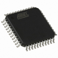
AT89C51ID2-RLTUM Atmel, AT89C51ID2-RLTUM Datasheet - Page 19

AT89C51ID2-RLTUM
Manufacturer Part Number
AT89C51ID2-RLTUM
Description
IC 8051 MCU FLASH 64K 44VQFP
Manufacturer
Atmel
Series
89Cr
Datasheet
1.AT89C51ID2-RLTUM.pdf
(157 pages)
Specifications of AT89C51ID2-RLTUM
Core Processor
8051
Core Size
8-Bit
Speed
60MHz
Connectivity
I²C, SPI, UART/USART
Peripherals
POR, PWM, WDT
Number Of I /o
34
Program Memory Size
64KB (64K x 8)
Program Memory Type
FLASH
Eeprom Size
2K x 8
Ram Size
2K x 8
Voltage - Supply (vcc/vdd)
2.7 V ~ 5.5 V
Oscillator Type
External
Operating Temperature
-40°C ~ 85°C
Package / Case
44-TQFP, 44-VQFP
Processor Series
AT89x
Core
8051
Data Bus Width
8 bit
Data Ram Size
2 KB
Interface Type
UART, SPI, TWI
Maximum Clock Frequency
60 MHz
Number Of Programmable I/os
34
Number Of Timers
3
Operating Supply Voltage
2.7 V to 5.5 V
Maximum Operating Temperature
+ 85 C
Mounting Style
SMD/SMT
3rd Party Development Tools
PK51, CA51, A51, ULINK2
Minimum Operating Temperature
- 40 C
Package
44VQFP
Device Core
8051
Family Name
89C
Maximum Speed
40 MHz
Height
1.45 mm
Length
10.1 mm
Supply Voltage (max)
5.5 V
Supply Voltage (min)
2.7 V
Width
10.1 mm
For Use With
AT89OCD-01 - USB EMULATOR FOR AT8XC51 MCU
Lead Free Status / RoHS Status
Lead free / RoHS Compliant
Data Converters
-
Lead Free Status / Rohs Status
Details
Available stocks
Company
Part Number
Manufacturer
Quantity
Price
Company:
Part Number:
AT89C51ID2-RLTUM
Manufacturer:
ATMEL
Quantity:
13 937
Design Considerations
Oscillators Control
Prescaler Divider
19
AT89C51ID2
Table 20. Overview (Continued)
•
•
•
•
•
•
•
PCON.1 PCON.0
0
1
PwdOscA and PwdOscB signals are generated in the Clock generator and used to
control the hard blocks of oscillators A and B.
PwdOscA =’1’ stops OscA
PwdOscB =’1’ stops OscB
The following tables summarize the Operating modes:
A hardware RESET puts the prescaler divider in the following state:
–
CKS signal selects OSCA or OSCB: F
Any value between FFh down to 00h can be written by software into CKRL register
in order to divide frequency of the selected oscillator:
–
–
PCON.1
PCON.1
CKRL = FFh: F
CKRL = 00h: minimum frequency
F
F
CKRL = FFh: maximum frequency
F
F
CLK CPU
CLK CPU
CLK CPU
CLK CPU
0
1
0
0
1
0
X
1
= F
= F
= F
= F
OscBEn OscAEn
CLK PERIPH
CLK PERIPH
CLK PERIPH
CLK PERIPH
1
X
CLK CPU
OscAEn
OscBEn
X
1
= F
= F
= F
= F
= F
1
X
0
1
X
0
OSCA
OSCA
OSCA
OSCA
CLK PERIPH
CKS
/1020 (Standard Mode)
/510 (X2 Mode)
X
0
/2 (Standard Mode)
(X2 Mode)
CLK OUT
IDLE MODE B
POWER DOWN
MODE
Selected Mode
= F
OSCA
= F
PwdOscA
PwdOscB
/2 (Standard C51 feature)
OSCA
0
1
1
0
1
1
or F
The CPU is off, OscB supplies the
peripherals, OscA can be disabled
(OscAEn = 0)
The CPU and peripherals are off,
OscA and OscB are stopped
OSCB
Comment
Power-down mode
Power-down mode
OscA stopped by
OscA stopped by
OscB stopped by
OscB stopped by
clearing OscAEn
clearing OscBEn
OscA running
OscB running
Comments
Comments
4289C–8051–11/05


