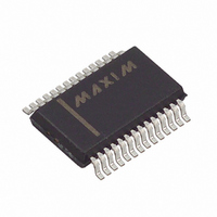
MAX1403EAI+ Maxim Integrated Products, MAX1403EAI+ Datasheet - Page 36

MAX1403EAI+
Manufacturer Part Number
MAX1403EAI+
Description
IC ADC 18BIT LP 28-SSOP
Manufacturer
Maxim Integrated Products
Datasheet
1.MAX1403EAI.pdf
(36 pages)
Specifications of MAX1403EAI+
Number Of Bits
18
Sampling Rate (per Second)
480
Data Interface
QSPI™, Serial, SPI™
Number Of Converters
1
Power Dissipation (max)
21.45mW
Voltage Supply Source
Analog and Digital
Operating Temperature
-40°C ~ 85°C
Mounting Type
Surface Mount
Package / Case
28-SSOP
Number Of Adc Inputs
5
Architecture
Delta-Sigma
Conversion Rate
4.8 KSPs
Resolution
18 bit
Input Type
Voltage
Interface Type
Serial
Voltage Reference
External
Supply Voltage (max)
3 V
Maximum Power Dissipation
21.45 mW
Maximum Operating Temperature
+ 85 C
Mounting Style
SMD/SMT
Input Signal Type
Pseudo-Differential, Differential
Minimum Operating Temperature
- 40 C
Lead Free Status / RoHS Status
Lead free / RoHS Compliant
Maxim cannot assume responsibility for use of any circuitry other than circuitry entirely embodied in a Maxim product. No circuit patent licenses are
implied. Maxim reserves the right to change the circuitry and specifications without notice at any time.
36 ____________________Maxim Integrated Products, 120 San Gabriel Drive, Sunnyvale, CA 94086 408-737-7600
© 2002 Maxim Integrated Products
Shield fast switching signals, such as clocks, with digi-
tal ground to avoid radiating noise to other sections of
the board. Avoid running clock signals near the analog
inputs. Avoid crossover of digital and analog signals.
Traces on opposite sides of the board should run at
right angles to each other. This will reduce the effects
of feedthrough on the board. A microstrip technique is
best but is not always possible with double-sided
boards. In this technique, the component side of the
board is dedicated to ground planes while signals are
placed on the solder side.
+5V, 18-Bit, Low-Power, Multichannel,
+3V, 18-Bit, Low-Power, Multichannel,
Oversampling (Sigma-Delta) ADC
Oversampling (Sigma-Delta) ADC
(The package drawing(s) in this data sheet may not reflect the most current specifications. For the latest package outline information
go to www.maxim-ic.com/packages.)
2. MOLD FLASH OR PROTRUSIONS NOT TO EXCEED .15 MM (.006").
3. CONTROLLING DIMENSION: MILLIMETERS.
5. LEADS TO BE COPLANAR WITHIN 0.10 MM.
NOTES:
1. D&E DO NOT INCLUDE MOLD FLASH.
4. MEETS JEDEC MO150.
e
D
2
B
1
N
Printed USA
A1
E
A
H
DIM
A
A1
B
C
D
E
e
H
L
0.025
0.068
0.002
0.010
0.004
0.205
0.301
0.0256 BSC
MIN
INCHES
0∞
L
Good decoupling is important when using high-resolu-
tion ADCs. Decouple all analog supplies with 10µF tan-
talum capacitors in parallel with 0.1µF HF ceramic
capacitors to AGND. Place these components as close
to the device as possible to achieve the best decou-
pling.
See the MAX1403 evaluation kit manual for the recom-
mended layout. The evaluation board package includes
a fully assembled and tested evaluation board.
SEE VARIATIONS
TRANSISTOR COUNT: 34,648
SUBSTRATE CONNECTED TO AGND
0.015
0.008
0.078
0.008
0.212
0.037
MAX
0.311
8∞
is a registered trademark of Maxim Integrated Products.
MILLIMETERS
0.25
0.09
5.20
7.65
0.63
MIN
1.73
0.05
0.65 BSC
0∞
1.99
0.38
0.20
MAX
5.38
0.95
0.21
7.90
8∞
TITLE:
APPROVAL
PROPRIETARY INFORMATION
PACKAGE OUTLINE, SSOP, 5.3 MM
D
D
D
D
D
0.278
0.317
0.397
0.239
0.239
MIN
Package Information
INCHES
DOCUMENT CONTROL NO.
0.249
0.249
0.289
0.328
0.407
MAX
Chip Information
21-0056
MILLIMETERS
10.07
MIN
6.07
7.07
8.07
6.07
10.33
MAX
6.33
6.33
7.33
8.33
C
REV.
C
14L
16L
20L
24L
28L
N
1
1


