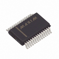
MAX1403EAI+ Maxim Integrated Products, MAX1403EAI+ Datasheet - Page 11

MAX1403EAI+
Manufacturer Part Number
MAX1403EAI+
Description
IC ADC 18BIT LP 28-SSOP
Manufacturer
Maxim Integrated Products
Datasheet
1.MAX1403EAI.pdf
(36 pages)
Specifications of MAX1403EAI+
Number Of Bits
18
Sampling Rate (per Second)
480
Data Interface
QSPI™, Serial, SPI™
Number Of Converters
1
Power Dissipation (max)
21.45mW
Voltage Supply Source
Analog and Digital
Operating Temperature
-40°C ~ 85°C
Mounting Type
Surface Mount
Package / Case
28-SSOP
Number Of Adc Inputs
5
Architecture
Delta-Sigma
Conversion Rate
4.8 KSPs
Resolution
18 bit
Input Type
Voltage
Interface Type
Serial
Voltage Reference
External
Supply Voltage (max)
3 V
Maximum Power Dissipation
21.45 mW
Maximum Operating Temperature
+ 85 C
Mounting Style
SMD/SMT
Input Signal Type
Pseudo-Differential, Differential
Minimum Operating Temperature
- 40 C
Lead Free Status / RoHS Status
Lead free / RoHS Compliant
PIN
10
11
12
13
14
15
16
17
18
1
2
3
4
5
6
7
8
9
CALGAIN+
CALGAIN-
CLKOUT
NAME
CLKIN
RESET
AGND
OUT2
OUT1
AIN1
AIN2
AIN3
AIN4
AIN5
AIN6
DS1
DS0
CS
V+
______________________________________________________________________________________
Clock Input. A crystal can be connected across CLKIN and CLKOUT. Alternatively, drive CLKIN with a
CMOS-compatible clock at a nominal frequency of 2.4576MHz or 1.024MHz, and leave CLKOUT uncon-
nected. Frequencies of 4.9152MHz and 2.048MHz may be used if the X2CLK control bit is set to 1.
Clock Output. When deriving the master clock from a crystal, connect the crystal between CLKIN and
CLKOUT. In this mode, the on-chip clock signal is not available at CLKOUT. Leave CLKOUT unconnected
when CLKIN is driven with an external clock.
Chip-Select Input. This active-low logic input is used to enable the digital interface. With CS hard-wired
low, the MAX1403 operates in its 3-wire interface mode with SCLK, DIN, and DOUT used to interface to
the device. CS is used either to select the device in systems with more than one device on the serial bus,
or as a frame-synchronization signal for the MAX1403, when a continuous SCLK is used.
Active-Low Reset Input. Drive low to reset the control logic, interface logic, digital filter, and analog modu-
lator to power-on status. RESET must be high and CLKIN must be toggling in order to exit reset.
Digital Input for Auxiliary Data Input Bit 1. The status of this bit is reflected in the output data by bit D4.
Used to communicate the status of DS1 via the serial interface.
Digital Input for Auxiliary Data Input Bit 0. The status of this bit is reflected in the output data by bit D3.
Used to communicate the status of DS0 via the serial interface.
Transducer Excitation Current Source 2
Transducer Excitation Current Source 1
Analog Ground. Reference point for the analog circuitry. AGND connects to the IC substrate.
Analog Positive Supply Voltage (+2.7V to +3.6V).
Analog Input Channel 1. May be used as a pseudo-differential input with AIN6 as common, or as the posi-
tive input of the AIN1/AIN2 differential analog input pair (see On-Chip Registers section).
Analog Input Channel 2. May be used as a pseudo-differential input with AIN6 as common, or as the neg-
ative input of the AIN1/AIN2 differential analog input pair (see On-Chip Registers section).
Analog Input Channel 3. May be used as a pseudo-differential input with AIN6 as common, or as the posi-
tive input of the AIN3/AIN4 differential analog input pair (see On-Chip Registers section).
Analog Input Channel 4. May be used as a pseudo-differential input with AIN6 as common, or as the neg-
ative input of the AIN3/AIN4 differential analog input pair (see On-Chip Registers section).
Analog Input Channel 5. Used as a differential or pseudo-differential input with AIN6 (see On-Chip
Registers section).
Analog Input 6. May be used as a common point for AIN1 through AIN5 in pseudo-differential mode, or as
the negative input of the AIN5/AIN6 differential analog input pair (see On-Chip Registers section).
Negative Gain Calibration Input. Used for system gain calibration. It forms the negative input of a fully
differential input pair with CALGAIN+. Normally these inputs are connected to reference voltages in the
system. When system gain calibration is not required and the auto-sequence mode is used, the
CALGAIN+/CALGAIN- input pair provides an additional fully differential input channel.
Positive Gain Calibration Input. Used for system gain calibration. It forms the positive input of a fully
differential input pair with CALGAIN-. Normally these inputs are connected to reference voltages in the
system. When system gain calibration is not required and the auto-sequence mode is used, the
CALGAIN+/CALGAIN- input pair provides an additional fully differential input channel.
+3V, 18-Bit, Low-Power, Multichannel,
Oversampling (Sigma-Delta) ADC
FUNCTION
Pin Description
11


