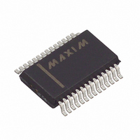
MAX1403EAI+ Maxim Integrated Products, MAX1403EAI+ Datasheet - Page 31

MAX1403EAI+
Manufacturer Part Number
MAX1403EAI+
Description
IC ADC 18BIT LP 28-SSOP
Manufacturer
Maxim Integrated Products
Datasheet
1.MAX1403EAI.pdf
(36 pages)
Specifications of MAX1403EAI+
Number Of Bits
18
Sampling Rate (per Second)
480
Data Interface
QSPI™, Serial, SPI™
Number Of Converters
1
Power Dissipation (max)
21.45mW
Voltage Supply Source
Analog and Digital
Operating Temperature
-40°C ~ 85°C
Mounting Type
Surface Mount
Package / Case
28-SSOP
Number Of Adc Inputs
5
Architecture
Delta-Sigma
Conversion Rate
4.8 KSPs
Resolution
18 bit
Input Type
Voltage
Interface Type
Serial
Voltage Reference
External
Supply Voltage (max)
3 V
Maximum Power Dissipation
21.45 mW
Maximum Operating Temperature
+ 85 C
Mounting Style
SMD/SMT
Input Signal Type
Pseudo-Differential, Differential
Minimum Operating Temperature
- 40 C
Lead Free Status / RoHS Status
Lead free / RoHS Compliant
Listing 1. Example SPI Interface
/* Assumptions:
**
**
**
*/
/* Low-level function to write 8 bits using 68HC11 SPI */
void WriteByte (BYTE x)
{
}
/* Low-level function to read 8 bits using 68HC11 SPI */
BYTE ReadByte (void)
{
}
/* Low-level interrupt handler called whenever the MAX140X's INT pin goes low.
** This function reads new data from the MAX140X and feeds it into a
** user-defined function Process_Data().
*/
void HandleDRDY (void)
{
}
/* High-level function to configure the MAX140X's registers
** Refer to data sheet for custom setup values.
*/
void Initialize (void)
{
}
The MAX140X's CS pin is tied to ground
The MAX140X's INT pin drives a falling-edge-triggered interrupt
MAX140X's DIN is driven by MOSI, DOUT drives MISO, and SCLK drives SCLK
/* System-dependent: write to SPI hardware and wait until it is finished */
HC11_SPDR = x;
while (HC11_SPSR & HC11_SPSR_SPIF) { /* idle loop */ }
/* System-dependent: use SPI hardware to clock in 8 bits */
HC11_SPDR = 0xFF;
while (HC11_SPSR & HC11_SPSR_SPIF) { /* idle loop */ }
return HC11_SPDR;
BYTE data_H_bits, data_M_bits, data_L_bits; /* storage for data register */
WriteByte(0x78);
data_H_bits = ReadByte();
data_M_bits = ReadByte();
data_L_bits = ReadByte();
Process_Data(data_H_bits, data_M_bits, data_L_bits);
/* System-dependent: re-enable the interrupt service routine */
/* System-dependent: configure the SPI hardware (CPOL=1,CPHA=1) */
/* write to all of configuration registers */
MY_GS1 = 0x0A; MY_GS2 = 0x00; MY_GS3 = 0x00;
MY_TF1 = 0x00; MY_TF2 = 0x00; MY_TF3 = 0x00;
WriteByte(0x10); WriteByte(MY_GS1); /* write Global Setup 1 */
WriteByte(0x20); WriteByte(MY_GS2); /* write Global Setup 2 */
WriteByte(0x30); WriteByte(MY_GS3); /* write Global Setup 3 */
WriteByte(0x40); WriteByte(MY_TF1); /* write Transfer Function 1 */
WriteByte(0x50); WriteByte(MY_TF2); /* write Transfer Function 2 */
WriteByte(0x60); WriteByte(MY_TF3); /* write Transfer Function 3 */
/* System-dependent: enable the data-ready (DRDY) interrupt handler */
______________________________________________________________________________________
+3V, 18-Bit, Low-Power, Multichannel,
Oversampling (Sigma-Delta) ADC
/* read the latest data regsiter value */
31


