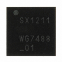
SX1211I084TRT Semtech, SX1211I084TRT Datasheet - Page 4

SX1211I084TRT
Manufacturer Part Number
SX1211I084TRT
Description
IC SNGL-CHIP TXRX 32-TQFN
Manufacturer
Semtech
Specifications of SX1211I084TRT
Frequency
860 ~ 960MHz
Data Rate - Maximum
200kbps
Modulation Or Protocol
FSK, OOK
Applications
AMR, ISM, Security and Access
Power - Output
12.5dBm
Sensitivity
-113dBm
Voltage - Supply
2.1 V ~ 3.6 V
Current - Receiving
3mA
Current - Transmitting
25mA
Data Interface
PCB, Surface Mount
Antenna Connector
PCB, Surface Mount
Operating Temperature
-40°C ~ 85°C
Package / Case
32-TQFN
Operating Temperature (min)
-40C
Operating Temperature (max)
85C
Operating Temperature Classification
Industrial
Modulation Type
FSK/OOK
Package Type
TQFN EP
Operating Supply Voltage (min)
2.1V
Operating Supply Voltage (typ)
2.5/3.3V
Operating Supply Voltage (max)
3.6V
Lead Free Status / RoHS Status
Lead free / RoHS Compliant
Memory Size
-
Lead Free Status / Rohs Status
Compliant
Other names
SX1211I084TRT
Available stocks
Company
Part Number
Manufacturer
Quantity
Price
Company:
Part Number:
SX1211I084TRT
Manufacturer:
HITTITE
Quantity:
560
Index of Tables
Table 1: Ordering Information....................................................... 1
Table 2: SX1211 Pinouts.............................................................. 7
Table 3: Absolute Maximum Ratings ............................................ 8
Table 4: Operating Range ............................................................ 8
Table 5: Power Consumption Specification................................... 8
Table 6: Frequency Synthesizer Specification .............................. 9
Table 7: Transmitter Specification ................................................ 9
Table 8: Receiver Specification .................................................. 10
Table 9: Digital Specification ...................................................... 11
Table 10: MCParam_Freq_band Setting..................................... 15
Table 11: PA Rise/Fall Times ..................................................... 20
Table 12: Operating Modes ........................................................ 33
Table 13: Pin Configuration vs. Chip Mode................................. 33
Table 14: Data Operation Mode Selection .................................. 35
Table 15: Config vs. Data SPI Interface Selection ...................... 36
Table 16: Status of FIFO when Switching Between Different
Modes of the Chip ...................................................................... 39
Table 17: Interrupt Mapping in Continuous Rx Mode .................. 42
Table 18: Interrupt Mapping in Continuous Tx Mode................... 42
Table 19: Relevant Config. Registers in Continuous Mode ........ 43
Acronyms
Rev 7 – Sept 2
ADVANCED COMMUNICATIONS & SENSING
BOM
BR
BW
CCITT
CP
CRC
DAC
DDS
DLL
ERP
ETSI
FCC
Fdev
FIFO
FS
FSK
GUI
IC
ID
IF
IRQ
ITU
LFSR
LNA
nd
Bill Of Materials
Bit Rate
Bandwidth
Comité Consultatif International
Téléphonique et Télégraphique - ITU
Charge Pump
Cyclic Redundancy Check
Digital to Analog Converter
Direct Digital Synthesis
Dynamically Linked Library
Equivalent Radiated Power
European Telecommunications Standards
Institute
Federal Communications Commission
Frequency Deviation
First In First Out
Frequency Synthesizer
Frequency Shift Keying
Graphical User Interface
Integrated Circuit
IDentificator
Intermediate Frequency
Interrupt ReQuest
International Telecommunication Union
Linear Feedback Shift Register
Low Noise Amplifier
, 2008
Page 4 of 92
Table 20: Interrupt Mapping in Buffered Rx and Stby Modes ...... 46
Table 21: Interrupt Mapping in Buffered Tx Mode ....................... 46
Table 22: Relevant Configuration Registers in Buffered Mode .... 47
Table 23: Interrupt Mapping in Rx and Stby in Packet Mode ....... 55
Table 24: Interrupt Mapping in Tx Packet Mode.......................... 55
Table 25: Relevant Configuration Registers in Packet Mode....... 56
Table 26: Registers List .............................................................. 58
Table 27: MCParam Register Description ................................... 58
Table 28: IRQParam Register Description .................................. 60
Table 29: RXParam Register Description.................................... 62
Table 30: SYNCParam Register Description............................... 63
Table 31: TXParam Register Description .................................... 64
Table 32: OSCParam Register Description................................. 64
Table 33: PKTParam Register Description.................................. 65
Table 34: Crystal Resonator Specification .................................. 66
Table 35: Reference Design BOM .............................................. 74
Table 36: Tools Ordering Information.......................................... 75
Table 37: FSK Rx Filters vs. Bit Rate.......................................... 76
Table 38: OOK Rx Filters vs. Bit Rate......................................... 76
LO
LSB
MSB
NRZ
NZIF
OOK
PA
PCB
PFD
PLL
POR
RBW
RF
RSSI
Rx
SAW
SPI
SR
Stby
Tx
uC
VCO
XO
XOR
Local Oscillator
Least Significant Bit
Most Significant Bit
Non Return to Zero
Near Zero Intermediate Frequency
On Off Keying
Power Amplifier
Printed Circuit Board
Phase Frequency Detector
Phase-Locked Loop
Power On Reset
Resolution BandWidth
Radio Frequency
Received Signal Strength Indicator
Receiver
Surface Acoustic Wave
Serial Peripheral Interface
Shift Register
Standby
Transmitter
Microcontroller
Voltage Controlled Oscillator
Crystal Oscillator
eXclusive OR
www.semtech.com
SX1211


