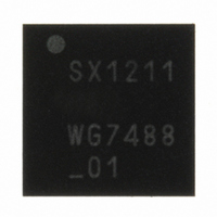
SX1211I084TRT Semtech, SX1211I084TRT Datasheet - Page 38

SX1211I084TRT
Manufacturer Part Number
SX1211I084TRT
Description
IC SNGL-CHIP TXRX 32-TQFN
Manufacturer
Semtech
Specifications of SX1211I084TRT
Frequency
860 ~ 960MHz
Data Rate - Maximum
200kbps
Modulation Or Protocol
FSK, OOK
Applications
AMR, ISM, Security and Access
Power - Output
12.5dBm
Sensitivity
-113dBm
Voltage - Supply
2.1 V ~ 3.6 V
Current - Receiving
3mA
Current - Transmitting
25mA
Data Interface
PCB, Surface Mount
Antenna Connector
PCB, Surface Mount
Operating Temperature
-40°C ~ 85°C
Package / Case
32-TQFN
Operating Temperature (min)
-40C
Operating Temperature (max)
85C
Operating Temperature Classification
Industrial
Modulation Type
FSK/OOK
Package Type
TQFN EP
Operating Supply Voltage (min)
2.1V
Operating Supply Voltage (typ)
2.5/3.3V
Operating Supply Voltage (max)
3.6V
Lead Free Status / RoHS Status
Lead free / RoHS Compliant
Memory Size
-
Lead Free Status / Rohs Status
Compliant
Other names
SX1211I084TRT
Available stocks
Company
Part Number
Manufacturer
Quantity
Price
Company:
Part Number:
SX1211I084TRT
Manufacturer:
HITTITE
Quantity:
560
To read bytes from the FIFO the timing diagram below should be carefully followed by the uC.
Note that it is compulsory to toggle NSS_DATA back high between each byte read.
In Buffered and Packet modes of operation, both data to be transmitted and that has been received are stored in a
configurable FIFO (First In First Out) device. It is accessed via the SPI Data interface and provides several
interrupts for transfer management.
The FIFO is 1 byte (8 bits) wide hence it only performs byte (parallel) operations, whereas the demodulator
functions serially. A shift register is therefore employed to interface the two devices. In transmit mode it takes bytes
from the FIFO and outputs them serially (MSB first) at the programmed bit rate to the modulator. Similarly, in Rx the
shift register gets bit by bit data from the demodulator and writes them byte by byte to the FIFO. This is illustrated in
figure below.
The FIFO width is programmable, to 16, 32, 48 or 64 bytes via MCParam_Fifo_size
Rev 7 – Sept 2
ADVANCED COMMUNICATIONS & SENSING
Read Byte (after/during Rx)
NSS_DATA (In)
SCK (In)
MOSI (In)
MISO (Out)
5.2.2. FIFO
nd
, 2008
HZ
(input)
5.2.2.1. Overview and Shift Register (SR)
5.2.2.2. Size Selection
D1(7)
1
x
D1(6) D1(5)
x
2
x
3
Data Tx/Rx
1
Figure 30: Read Bytes Sequence (ex: 2 bytes)
D1(4) D1(3)
st
4
x
byte read
Figure 31: FIFO and Shift Register (SR)
5
x
1
D1(2) D1(1)
6
x
MSB
7
x
Page 38 of 92
D1(0)
8
x
SR (8bits)
x
(input)
byte1
byte0
HZ
8
D2(7) D2(6)
1
x
2
x
LSB
D2(5)
3
x
FIFO
2
D2(4)
nd
4
x
byte read
D2(3)
5
x
D2(2)
6
x
D2(1)
7
x
D2(0)
8
x
www.semtech.com
SX1211
HZ
(input)


