TOOLSTICK560DC Silicon Laboratories Inc, TOOLSTICK560DC Datasheet - Page 290
TOOLSTICK560DC
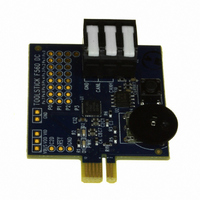
Manufacturer Part Number
TOOLSTICK560DC
Description
DAUGHTER CARD TOOLSTICK F560
Manufacturer
Silicon Laboratories Inc
Series
ToolStickr
Type
MCUr
Specifications of TOOLSTICK560DC
Contents
Daughter Card
Processor To Be Evaluated
C8051F55x, C8051F56x, C8051F57x
Interface Type
USB
Operating Supply Voltage
2.7 V to 3.6 V
Lead Free Status / RoHS Status
Lead free / RoHS Compliant
For Use With/related Products
C8051F55x, C8051F56x, C8051F57x
For Use With
336-1345 - TOOLSTICK BASE ADAPTER336-1182 - ADAPTER USB DEBUG FOR C8051FXXX
Lead Free Status / Rohs Status
Lead free / RoHS Compliant
Other names
336-1719


C8051F55x/56x/57x
26.5. Register Descriptions for PCA0
Following are detailed descriptions of the special function registers related to the operation of the PCA.
SFR Definition 26.1. PCA0CN: PCA Control
SFR Address = 0xD8; Bit-Addressable; SFR Page = 0x00
290
Name
Reset
Bit
Type
7
6
5
4
3
2
1
0
Bit
Name
CCF5
CCF4
CCF3
CCF2
CCF1
CCF0
CF
CR
R/W
CF
7
0
PCA Counter/Timer Overflow Flag.
Set by hardware when the PCA Counter/Timer overflows from 0xFFFF to 0x0000.
When the Counter/Timer Overflow (CF) interrupt is enabled, setting this bit causes the
CPU to vector to the PCA interrupt service routine. This bit is not automatically cleared
by hardware and must be cleared by software.
PCA Counter/Timer Run Control.
This bit enables/disables the PCA Counter/Timer.
0: PCA Counter/Timer disabled.
1: PCA Counter/Timer enabled.
PCA Module 5 Capture/Compare Flag.
This bit is set by hardware when a match or capture occurs. When the CCF5 interrupt
is enabled, setting this bit causes the CPU to vector to the PCA interrupt service rou-
tine. This bit is not automatically cleared by hardware and must be cleared by software.
PCA Module 4 Capture/Compare Flag.
This bit is set by hardware when a match or capture occurs. When the CCF4 interrupt
is enabled, setting this bit causes the CPU to vector to the PCA interrupt service rou-
tine. This bit is not automatically cleared by hardware and must be cleared by software.
PCA Module 3 Capture/Compare Flag.
This bit is set by hardware when a match or capture occurs. When the CCF3 interrupt
is enabled, setting this bit causes the CPU to vector to the PCA interrupt service rou-
tine. This bit is not automatically cleared by hardware and must be cleared by software.
PCA Module 2 Capture/Compare Flag.
This bit is set by hardware when a match or capture occurs. When the CCF2 interrupt
is enabled, setting this bit causes the CPU to vector to the PCA interrupt service rou-
tine. This bit is not automatically cleared by hardware and must be cleared by software.
PCA Module 1 Capture/Compare Flag.
This bit is set by hardware when a match or capture occurs. When the CCF1 interrupt
is enabled, setting this bit causes the CPU to vector to the PCA interrupt service rou-
tine. This bit is not automatically cleared by hardware and must be cleared by software.
PCA Module 0 Capture/Compare Flag.
This bit is set by hardware when a match or capture occurs. When the CCF0 interrupt
is enabled, setting this bit causes the CPU to vector to the PCA interrupt service rou-
tine. This bit is not automatically cleared by hardware and must be cleared by software.
R/W
CR
6
0
CCF5
R/W
5
0
CCF4
R/W
Rev. 1.1
4
0
Function
CCF3
R/W
3
0
CCF2
R/W
2
0
CCF1
R/W
1
0
CCF0
R/W
0
0
Related parts for TOOLSTICK560DC
Image
Part Number
Description
Manufacturer
Datasheet
Request
R

Part Number:
Description:
KIT TOOL EVAL SYS IN A USB STICK
Manufacturer:
Silicon Laboratories Inc
Datasheet:

Part Number:
Description:
TOOLSTICK DEBUG ADAPTER
Manufacturer:
Silicon Laboratories Inc
Datasheet:

Part Number:
Description:
TOOLSTICK BASE ADAPTER
Manufacturer:
Silicon Laboratories Inc
Datasheet:

Part Number:
Description:
TOOLSTICK DAUGHTER CARD
Manufacturer:
Silicon Laboratories Inc
Datasheet:

Part Number:
Description:
TOOLSTICK DAUGHTER CARD
Manufacturer:
Silicon Laboratories Inc
Datasheet:

Part Number:
Description:
TOOLSTICK DAUGHTER CARD
Manufacturer:
Silicon Laboratories Inc
Datasheet:

Part Number:
Description:
TOOLSTICK PROGRAMMING ADAPTER
Manufacturer:
Silicon Laboratories Inc
Datasheet:

Part Number:
Description:
TOOLSTICK DAUGHTER CARD
Manufacturer:
Silicon Laboratories Inc
Datasheet:

Part Number:
Description:
KIT STARTER TOOLSTICK
Manufacturer:
Silicon Laboratories Inc
Datasheet:

Part Number:
Description:
KIT UNIVERSITY TOOLSTICK STARTER
Manufacturer:
Silicon Laboratories Inc
Datasheet:

Part Number:
Description:
DAUGHTER CARD TOOLSTICK F330
Manufacturer:
Silicon Laboratories Inc
Datasheet:

Part Number:
Description:
CARD DAUGHTER UNIVRSTY TOOLSTICK
Manufacturer:
Silicon Laboratories Inc
Datasheet:

Part Number:
Description:
DAUGHTER CARD TOOLSTICK F582
Manufacturer:
Silicon Laboratories Inc
Datasheet:

Part Number:
Description:
DAUGHTER CARD TOOLSTICK F500
Manufacturer:
Silicon Laboratories Inc
Datasheet:

Part Number:
Description:
DAUGHTER CARD TOOLSTICK F540
Manufacturer:
Silicon Laboratories Inc
Datasheet: