TOOLSTICK560DC Silicon Laboratories Inc, TOOLSTICK560DC Datasheet - Page 112
TOOLSTICK560DC
Manufacturer Part Number
TOOLSTICK560DC
Description
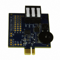
DAUGHTER CARD TOOLSTICK F560
Manufacturer
Silicon Laboratories Inc
Series
ToolStickr
Type
MCUr
Specifications of TOOLSTICK560DC
Contents
Daughter Card
Processor To Be Evaluated
C8051F55x, C8051F56x, C8051F57x
Interface Type
USB
Operating Supply Voltage
2.7 V to 3.6 V
Lead Free Status / RoHS Status
Lead free / RoHS Compliant
For Use With/related Products
C8051F55x, C8051F56x, C8051F57x
For Use With
336-1345 - TOOLSTICK BASE ADAPTER336-1182 - ADAPTER USB DEBUG FOR C8051FXXX
Lead Free Status / Rohs Status
Lead free / RoHS Compliant
Other names
336-1719


C8051F55x/56x/57x
13. Interrupts
The C8051F55x/56x/57x devices include an extended interrupt system supporting a total of 18 interrupt
sources with two priority levels. The allocation of interrupt sources between on-chip peripherals and exter-
nal inputs pins varies according to the specific version of the device. Each interrupt source has one or
more associated interrupt-pending flag(s) located in an SFR. When a peripheral or external source meets
a valid interrupt condition, the associated interrupt-pending flag is set to logic 1.
If interrupts are enabled for the source, an interrupt request is generated when the interrupt-pending flag is
set. As soon as execution of the current instruction is complete, the CPU generates an LCALL to a prede-
termined address to begin execution of an interrupt service routine (ISR). Each ISR must end with an RETI
instruction, which returns program execution to the next instruction that would have been executed if the
interrupt request had not occurred. If interrupts are not enabled, the interrupt-pending flag is ignored by the
hardware and program execution continues as normal. (The interrupt-pending flag is set to logic 1 regard-
less of the interrupt's enable/disable state.)
Each interrupt source can be individually enabled or disabled through the use of an associated interrupt
enable bit in an SFR (IE, EIE1, or EIE2). However, interrupts must first be globally enabled by setting the
EA bit (IE.7) to logic 1 before the individual interrupt enables are recognized. Setting the EA bit to logic 0
disables all interrupt sources regardless of the individual interrupt-enable settings.
Note: Any instruction that clears a bit to disable an interrupt should be immediately followed by an instruction that has
two or more opcode bytes. Using EA (global interrupt enable) as an example:
// in 'C':
EA = 0; // clear EA bit.
EA = 0; // this is a dummy instruction with two-byte opcode.
; in assembly:
CLR EA ; clear EA bit.
CLR EA ; this is a dummy instruction with two-byte opcode.
For example, if an interrupt is posted during the execution phase of a "CLR EA" opcode (or any instruction
which clears a bit to disable an interrupt source), and the instruction is followed by a single-cycle instruc-
tion, the interrupt may be taken. However, a read of the enable bit will return a 0 inside the interrupt service
routine. When the bit-clearing opcode is followed by a multi-cycle instruction, the interrupt will not be taken.
Some interrupt-pending flags are automatically cleared by the hardware when the CPU vectors to the ISR.
However, most are not cleared by the hardware and must be cleared by software before returning from the
ISR. If an interrupt-pending flag remains set after the CPU completes the return-from-interrupt (RETI)
instruction, a new interrupt request will be generated immediately and the CPU will re-enter the ISR after
the completion of the next instruction.
13.1. MCU Interrupt Sources and Vectors
The C8051F55x/56x/57x MCUs support 18 interrupt sources. Software can simulate an interrupt by setting
any interrupt-pending flag to logic 1. If interrupts are enabled for the flag, an interrupt request will be gener-
ated and the CPU will vector to the ISR address associated with the interrupt-pending flag. MCU interrupt
sources, associated vector addresses, priority order and control bits are summarized in Table 13.1. Refer
to the datasheet section associated with a particular on-chip peripheral for information regarding valid
interrupt conditions for the peripheral and the behavior of its interrupt-pending flag(s).
112
Rev. 1.1
Related parts for TOOLSTICK560DC
Image
Part Number
Description
Manufacturer
Datasheet
Request
R

Part Number:
Description:
KIT TOOL EVAL SYS IN A USB STICK
Manufacturer:
Silicon Laboratories Inc
Datasheet:

Part Number:
Description:
TOOLSTICK DEBUG ADAPTER
Manufacturer:
Silicon Laboratories Inc
Datasheet:

Part Number:
Description:
TOOLSTICK BASE ADAPTER
Manufacturer:
Silicon Laboratories Inc
Datasheet:

Part Number:
Description:
TOOLSTICK DAUGHTER CARD
Manufacturer:
Silicon Laboratories Inc
Datasheet:

Part Number:
Description:
TOOLSTICK DAUGHTER CARD
Manufacturer:
Silicon Laboratories Inc
Datasheet:

Part Number:
Description:
TOOLSTICK DAUGHTER CARD
Manufacturer:
Silicon Laboratories Inc
Datasheet:

Part Number:
Description:
TOOLSTICK PROGRAMMING ADAPTER
Manufacturer:
Silicon Laboratories Inc
Datasheet:

Part Number:
Description:
TOOLSTICK DAUGHTER CARD
Manufacturer:
Silicon Laboratories Inc
Datasheet:

Part Number:
Description:
KIT STARTER TOOLSTICK
Manufacturer:
Silicon Laboratories Inc
Datasheet:

Part Number:
Description:
KIT UNIVERSITY TOOLSTICK STARTER
Manufacturer:
Silicon Laboratories Inc
Datasheet:

Part Number:
Description:
DAUGHTER CARD TOOLSTICK F330
Manufacturer:
Silicon Laboratories Inc
Datasheet:

Part Number:
Description:
CARD DAUGHTER UNIVRSTY TOOLSTICK
Manufacturer:
Silicon Laboratories Inc
Datasheet:

Part Number:
Description:
DAUGHTER CARD TOOLSTICK F582
Manufacturer:
Silicon Laboratories Inc
Datasheet:

Part Number:
Description:
DAUGHTER CARD TOOLSTICK F500
Manufacturer:
Silicon Laboratories Inc
Datasheet:

Part Number:
Description:
DAUGHTER CARD TOOLSTICK F540
Manufacturer:
Silicon Laboratories Inc
Datasheet: