TOOLSTICK560DC Silicon Laboratories Inc, TOOLSTICK560DC Datasheet - Page 209
TOOLSTICK560DC
Manufacturer Part Number
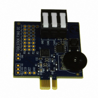
TOOLSTICK560DC
Description
DAUGHTER CARD TOOLSTICK F560
Manufacturer
Silicon Laboratories Inc
Series
ToolStickr
Type
MCUr
Specifications of TOOLSTICK560DC
Contents
Daughter Card
Processor To Be Evaluated
C8051F55x, C8051F56x, C8051F57x
Interface Type
USB
Operating Supply Voltage
2.7 V to 3.6 V
Lead Free Status / RoHS Status
Lead free / RoHS Compliant
For Use With/related Products
C8051F55x, C8051F56x, C8051F57x
For Use With
336-1345 - TOOLSTICK BASE ADAPTER336-1182 - ADAPTER USB DEBUG FOR C8051FXXX
Lead Free Status / Rohs Status
Lead free / RoHS Compliant
Other names
336-1719


21.1. Bosch CAN Controller Operation
The CAN Controller featured in the C8051F550/1/4/5, ‘F560/1/4/5/8/9, and ‘F572/3 devices is a full imple-
mentation of Bosch’s full CAN module and fully complies with CAN specification 2.0B. A block diagram of
the CAN controller is shown in Figure 21.2. The CAN Core provides shifting (CANTX and CANRX), serial/
parallel conversion of messages, and other protocol related tasks such as transmission of data and accep-
tance filtering. The message RAM stores 32 message objects which can be received or transmitted on a
CAN network. The CAN registers and message handler provide an interface for data transfer and notifica-
tion between the CAN controller and the CIP-51.
The function and use of the CAN Controller is detailed in the Bosch CAN User’s Guide. The User’s Guide
should be used as a reference to configure and use the CAN controller. This data sheet describes how to
access the CAN controller.
All of the CAN controller registers are located on SFR Page 0x0C. Before accessing any of the CAN regis-
ters, the SFRPAGE register must be set to 0x0C.
The CAN Controller is typically initialized using the following steps:
1. Set the SFRPAGE register to the CAN registers page (page 0x0C).
2. Set the INIT and the CCE bits to 1 in CAN0CN. See the CAN User’s Guide for bit definitions.
3. Set timing parameters in the Bit Timing Register and the BRP Extension Register.
4. Initialize each message object or set its MsgVal bit to NOT VALID.
5. Reset the INIT bit to 0.
21.1.1. CAN Controller Timing
The CAN controller’s clock (f
is accurate to within 0.5% of 24 MHz across the entire temperature range and for VDD voltages greater
than or equal to the minimum output of the on-chip voltage regulator, so an external oscillator is not
required for CAN communication for most systems.
Refer to Section “4.10.4 Oscillator Tolerance Range” in the Bosch CAN User’s Guide for further informa-
tion regarding this topic.
CAN Controller
(32 Objects)
Message
Message
Handler
RAM
sys
) is derived from the CIP-51 system clock (SYSCLK). The internal oscillator
Figure 21.2. CAN Controller Diagram
RX
CAN Core
Rev. 1.1
TX
CAN0CFG
C8051F55x/56x/57x
System Clock
8051 MCU Core
CAN Registers
SFR space
mapped to
209
Related parts for TOOLSTICK560DC
Image
Part Number
Description
Manufacturer
Datasheet
Request
R

Part Number:
Description:
KIT TOOL EVAL SYS IN A USB STICK
Manufacturer:
Silicon Laboratories Inc
Datasheet:

Part Number:
Description:
TOOLSTICK DEBUG ADAPTER
Manufacturer:
Silicon Laboratories Inc
Datasheet:

Part Number:
Description:
TOOLSTICK BASE ADAPTER
Manufacturer:
Silicon Laboratories Inc
Datasheet:

Part Number:
Description:
TOOLSTICK DAUGHTER CARD
Manufacturer:
Silicon Laboratories Inc
Datasheet:

Part Number:
Description:
TOOLSTICK DAUGHTER CARD
Manufacturer:
Silicon Laboratories Inc
Datasheet:

Part Number:
Description:
TOOLSTICK DAUGHTER CARD
Manufacturer:
Silicon Laboratories Inc
Datasheet:

Part Number:
Description:
TOOLSTICK PROGRAMMING ADAPTER
Manufacturer:
Silicon Laboratories Inc
Datasheet:

Part Number:
Description:
TOOLSTICK DAUGHTER CARD
Manufacturer:
Silicon Laboratories Inc
Datasheet:

Part Number:
Description:
KIT STARTER TOOLSTICK
Manufacturer:
Silicon Laboratories Inc
Datasheet:

Part Number:
Description:
KIT UNIVERSITY TOOLSTICK STARTER
Manufacturer:
Silicon Laboratories Inc
Datasheet:

Part Number:
Description:
DAUGHTER CARD TOOLSTICK F330
Manufacturer:
Silicon Laboratories Inc
Datasheet:

Part Number:
Description:
CARD DAUGHTER UNIVRSTY TOOLSTICK
Manufacturer:
Silicon Laboratories Inc
Datasheet:

Part Number:
Description:
DAUGHTER CARD TOOLSTICK F582
Manufacturer:
Silicon Laboratories Inc
Datasheet:

Part Number:
Description:
DAUGHTER CARD TOOLSTICK F500
Manufacturer:
Silicon Laboratories Inc
Datasheet:

Part Number:
Description:
DAUGHTER CARD TOOLSTICK F540
Manufacturer:
Silicon Laboratories Inc
Datasheet: