P0528 Terasic Technologies Inc, P0528 Datasheet - Page 12
P0528
Manufacturer Part Number
P0528
Description
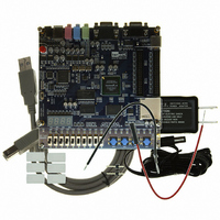
BOARD DEV DE1 ALTERA
Manufacturer
Terasic Technologies Inc
Type
FPGAr
Datasheet
1.P0528.pdf
(56 pages)
Specifications of P0528
Contents
DE1 Board, Power Supply, USB Cable, Plastic cover and software
For Use With/related Products
Cyclone II 2C20
For Use With
P0033 - BOARD ADAPTER HSMC TO GPIOP0006 - BOARD ADAPTER THDB-SUMP0001 - MODULE DIGITAL CAMERA 5MP (D5M)P0307 - KIT DEV 4.3" LCD TOUCH PANEL
Lead Free Status / RoHS Status
Lead free / RoHS Compliant
Other names
DE1


The DE1 board comes with a Control Panel facility that allows a user to access various components
on the board through a USB connection from a host computer. This chapter first presents some
basic functions of the Control Panel, then describes its structure in block diagram form, and finally
describes its capabilities.
3.1 Control Panel Setup
To run the Control Panel application, it is first necessary to configure a corresponding circuit in the
Cyclone II FPGA. This is done by downloading the configuration file
FPGA. The downloading procedure is described in Section 4.1.
In addition to the
program DE1_control_panel.exe. Both of these files are available on the DE1 System CD-ROM
that accompanies the DE1 board, in the directory DE1_control_panel. Of course, these files may
already have been installed to some other location on your computer system.
To activate the Control Panel, perform the following steps:
1. Connect the supplied USB cable to the USB Blaster port, connect the 9V power supply,
2. Set the RUN/PROG switch to the RUN position
3. Start the Quartus II software
4. Select Tools > Programmer to reach the window in Figure 3.1. Click on Add File and in
5. Start the executable DE1_control_panel.exe on the host computer. The Control Panel user
6. Open the USB port by clicking Open > Open USB Port 0. The DE1 Control Panel
and turn the power switch ON
the pop-up window that appears select the DE1_USB_API.sof file. Next, click on the
Program/Configure box which results in the image displayed in the figure. Now, click
Start to download the configuration file into the FPGA.
interface shown in Figure 3.2 will appear.
application will list all the USB ports that connect to DE1 boards. The DE1 Control Panel
can control up to 4 DE1 boards using the USB links.
USB port until you close that port; you cannot use Quartus II to download a configuration
file into the FPGA until you close the USB port.
DE1_USB_API.sof
DE1 Control Panel
Chapter 3
file, it is necessary to execute on the host computer the
10
The Control Panel will occupy the
DE1_USB_API.sof
DE1 User Manual
into the
Related parts for P0528
Image
Part Number
Description
Manufacturer
Datasheet
Request
R

Part Number:
Description:
MODULE DIGITAL CAMERA 5MP (D5M)
Manufacturer:
Terasic Technologies Inc
Datasheet:

Part Number:
Description:
DE2-70 CALL FOR ACADEMIC PRICING
Manufacturer:
Terasic Technologies Inc
Datasheet:

Part Number:
Description:
USB BLASTER CABLE
Manufacturer:
Terasic Technologies Inc
Datasheet:

Part Number:
Description:
BOARD ADAPTER HSMC TO GPIO
Manufacturer:
Terasic Technologies Inc
Datasheet:

Part Number:
Description:
BOARD ADAPTER THDB-SUM
Manufacturer:
Terasic Technologies Inc
Datasheet:

Part Number:
Description:
KIT DEV 4.3" LCD TOUCH PANEL
Manufacturer:
Terasic Technologies Inc
Datasheet:

Part Number:
Description:
DAUGHTER BOARD AD/DA GPIO ADA
Manufacturer:
Terasic Technologies Inc

Part Number:
Description:
DAUGHTER BOARD AD/DA HSMC ADA
Manufacturer:
Terasic Technologies Inc

Part Number:
Description:
KIT MAX II MICRO
Manufacturer:
Terasic Technologies Inc
Datasheet:

Part Number:
Description:
BOARD DEV/EDUCATION ALTERA DE0
Manufacturer:
Terasic Technologies Inc
Datasheet:

Part Number:
Description:
DE2 CALL FOR ACADEMIC PRICING
Manufacturer:
Terasic Technologies Inc

Part Number:
Description:
MODULE DIGITAL CAMERA 1.3MP
Manufacturer:
Terasic Technologies Inc
Datasheet:

Part Number:
Description:
SENSOR CMOS 1.3MEGA (FOR P0349)
Manufacturer:
Terasic Technologies Inc
Datasheet:
Part Number:
Description:
MODULE DIGITAL CAMERA 5MP (D5M)
Manufacturer:
Terasic Technologies Inc
Datasheet: