P0528 Terasic Technologies Inc, P0528 Datasheet - Page 10
P0528
Manufacturer Part Number
P0528
Description
BOARD DEV DE1 ALTERA
Manufacturer
Terasic Technologies Inc
Type
FPGAr
Datasheet
1.P0528.pdf
(56 pages)
Specifications of P0528
Contents
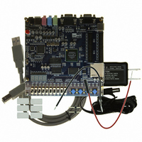
DE1 Board, Power Supply, USB Cable, Plastic cover and software
For Use With/related Products
Cyclone II 2C20
For Use With
P0033 - BOARD ADAPTER HSMC TO GPIOP0006 - BOARD ADAPTER THDB-SUMP0001 - MODULE DIGITAL CAMERA 5MP (D5M)P0307 - KIT DEV 4.3" LCD TOUCH PANEL
Lead Free Status / RoHS Status
Lead free / RoHS Compliant
Other names
DE1


VGA output
Serial ports
Two 40-pin expansion headers
2.3 Power-up the DE1 Board
The DE1 board comes with a preloaded configuration bit stream to demonstrate some features of
the board. This bit stream also allows users to see quickly if the board is working properly. To
power-up the board perform the following steps:
At this point you should observe the following:
• Applications for MP3 players and recorders, PDAs, smart phones, voice recorders, etc.
• Uses a 4-bit resistor-network DAC
• With 15-pin high-density D-sub connector
• Supports up to 640x480 at 60-Hz refresh rate
• Can be used with the Cyclone II FPGA to implement a high-performance TV Encoder
• One RS-232 port
• One PS/2 port
• DB-9 serial connector for the RS-232 port
• PS/2 connector for connecting a PS2 mouse or keyboard to the DE1 board
• 72 Cyclone II I/O pins, as well as 8 power and ground lines, are brought out to two 40-pin
• 40-pin header is designed to accept a standard 40-pin ribbon cable used for IDE hard drives
• Resistor protection is provided
1. Connect the provided USB cable from the host computer to the USB Blaster connector on
2. Connect the 7.5V adapter to the DE1 board
3. Connect a VGA monitor to the VGA port on the DE1 board
4. Connect your headset to the Line-out audio port on the DE1 board
5. Turn the RUN/PROG switch on the left edge of the DE1 board to RUN position; the
6. Turn the power on by pressing the ON/OFF switch on the DE1 board
expansion connectors
the DE1 board. For communication between the host and the DE1 board, it is necessary to
install the Altera USB Blaster driver software. If this driver is not already installed on the
host computer, it can be installed as explained in the tutorial
DE1 Board.
DE1 web pages.
PROG position is used only for the AS Mode programming
This tutorial is available on the DE1 System CD-ROM and from the Altera
8
Getting Started with Altera's
DE1 User Manual
Related parts for P0528
Image
Part Number
Description
Manufacturer
Datasheet
Request
R

Part Number:
Description:
MODULE DIGITAL CAMERA 5MP (D5M)
Manufacturer:
Terasic Technologies Inc
Datasheet:

Part Number:
Description:
DE2-70 CALL FOR ACADEMIC PRICING
Manufacturer:
Terasic Technologies Inc
Datasheet:

Part Number:
Description:
USB BLASTER CABLE
Manufacturer:
Terasic Technologies Inc
Datasheet:

Part Number:
Description:
BOARD ADAPTER HSMC TO GPIO
Manufacturer:
Terasic Technologies Inc
Datasheet:

Part Number:
Description:
BOARD ADAPTER THDB-SUM
Manufacturer:
Terasic Technologies Inc
Datasheet:

Part Number:
Description:
KIT DEV 4.3" LCD TOUCH PANEL
Manufacturer:
Terasic Technologies Inc
Datasheet:

Part Number:
Description:
DAUGHTER BOARD AD/DA GPIO ADA
Manufacturer:
Terasic Technologies Inc

Part Number:
Description:
DAUGHTER BOARD AD/DA HSMC ADA
Manufacturer:
Terasic Technologies Inc

Part Number:
Description:
KIT MAX II MICRO
Manufacturer:
Terasic Technologies Inc
Datasheet:

Part Number:
Description:
BOARD DEV/EDUCATION ALTERA DE0
Manufacturer:
Terasic Technologies Inc
Datasheet:

Part Number:
Description:
DE2 CALL FOR ACADEMIC PRICING
Manufacturer:
Terasic Technologies Inc

Part Number:
Description:
MODULE DIGITAL CAMERA 1.3MP
Manufacturer:
Terasic Technologies Inc
Datasheet:

Part Number:
Description:
SENSOR CMOS 1.3MEGA (FOR P0349)
Manufacturer:
Terasic Technologies Inc
Datasheet:
Part Number:
Description:
MODULE DIGITAL CAMERA 5MP (D5M)
Manufacturer:
Terasic Technologies Inc
Datasheet: