ATSTK500 Atmel, ATSTK500 Datasheet - Page 8
ATSTK500
Manufacturer Part Number
ATSTK500
Description
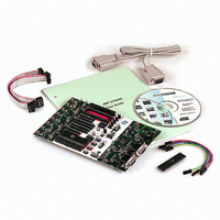
PROGRAMMER AVR STARTER KIT
Manufacturer
Atmel
Series
AVR®r
Type
MCUr
Specifications of ATSTK500
Contents
Board, Cable, CD and Documentation
Data Bus Width
8 bit
Interface Type
RS-232
For Use With/related Products
Atmel AVR Devices
For Use With
ATADAPCAN01 - EXTENSION CAN ADD-ON TO STK500/1
Lead Free Status / RoHS Status
Lead free / RoHS Compliant


1925C–AVR–3/03
Getting Started
2.3
2-2
Quick Start
The STK500 starter kit is shipped with an AT90S8515-8PC microcontroller in the socket
marked SCKT3000D3. The default jumper settings will allow the microcontroller to exe-
cute from the clock source and voltage regulator on the STK500 board.
The microcontroller is programmed with a test program that toggles the LEDs. The test
program in the AT90S8515 is similar to the example application code described in Sec-
tion 9. Connect the LEDs and switches and power up the STK500 to run the test
program in the AT90S8515.
Use the supplied 10-pin cables to connect the header marked “PORTB” with the header
marked “LEDS”, and connect the header marked “PORTD” with the header marked
“SWITCHES”. The connections are shown in Figure 2-1.
An external 10 - 15V DC power supply is required. The input circuit is a full bridge recti-
fier, and the STK500 automatically handles both positive or negative center connectors.
If a positive center connector is used, it can be impossible to turn the STK500 off since
the power switch disconnects the GND terminal. In this case, GND can be supplied
through the RS-232 cable shield if connected or through alternative GND connections.
Connect the power cable between a power supply and the STK500. Apply 10 - 15V DC
to the power connector. The power switch turns the STK500 main power on and off. The
red LED is lit when power is on, and the status LEDs will go from red, via yellow, to
green. The green LED indicates that the target V
ning in the AT90S8515 will respond to pressed switches by toggling the LEDs.
Figure 2-1. Default Setup of STK500
The starter kit can be configured for various clock and power sources. A complete
description of the jumper settings is explained in paragraph 3.8 on page 3-15 and on the
reverse side of the starter kit.
CC
is present. The program now run-
AVR STK500 User Guide
Related parts for ATSTK500
Image
Part Number
Description
Manufacturer
Datasheet
Request
R

Part Number:
Description:
DEV KIT FOR AVR/AVR32
Manufacturer:
Atmel
Datasheet:

Part Number:
Description:
INTERVAL AND WIPE/WASH WIPER CONTROL IC WITH DELAY
Manufacturer:
ATMEL Corporation
Datasheet:
Part Number:
Description:
Low-Voltage Voice-Switched IC for Hands-Free Operation
Manufacturer:
ATMEL Corporation
Datasheet:
Part Number:
Description:
MONOLITHIC INTEGRATED FEATUREPHONE CIRCUIT
Manufacturer:
ATMEL Corporation
Datasheet:
Part Number:
Description:
AM-FM Receiver IC U4255BM-M
Manufacturer:
ATMEL Corporation
Datasheet:
Part Number:
Description:
Monolithic Integrated Feature Phone Circuit
Manufacturer:
ATMEL Corporation
Datasheet:
Part Number:
Description:
Multistandard Video-IF and Quasi Parallel Sound Processing
Manufacturer:
ATMEL Corporation
Datasheet:
Part Number:
Description:
High-performance EE PLD
Manufacturer:
ATMEL Corporation
Datasheet:
Part Number:
Description:
8-bit Flash Microcontroller
Manufacturer:
ATMEL Corporation
Datasheet:
Part Number:
Description:
2-Wire Serial EEPROM
Manufacturer:
ATMEL Corporation
Datasheet: