ATSTK500 Atmel, ATSTK500 Datasheet - Page 36
ATSTK500
Manufacturer Part Number
ATSTK500
Description
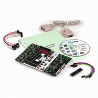
PROGRAMMER AVR STARTER KIT
Manufacturer
Atmel
Series
AVR®r
Type
MCUr
Specifications of ATSTK500
Contents
Board, Cable, CD and Documentation
Data Bus Width
8 bit
Interface Type
RS-232
For Use With/related Products
Atmel AVR Devices
For Use With
ATADAPCAN01 - EXTENSION CAN ADD-ON TO STK500/1
Lead Free Status / RoHS Status
Lead free / RoHS Compliant


1925C–AVR–3/03
Hardware Description
3.11
3.11.1
3-26
Miscellaneous
RESET Push Button
Figure 3-37. Prog Data Header Pinout
The Prog Data signals are used for the data bus when parallel High-voltage Program-
ming an AVR device. During ISP programming, DATA5 is used as MOSI, DATA6 is
used as MISO, and DATA7 is used for SCK.
Note:
STK500 has 2 push buttons and 3 LEDs for special functions and status indication. The
following section explains these features. Figure 3-38 shows the placement of these
functions.
Figure 3-38. Special Functions and Status Indication LEDs
The RESET push button resets the target AVR device when pushed. The master micro-
controller is not controlled by the RESET push button. When the RESET jumper is not
mounted, the RESET push button is disabled.
All Prog Data signals are based on 5V CMOS logic. No voltage conversion to
adapt to VTG is done on these signals.
Target Power LED
DATA0
DATA2
DATA4
DATA6
Status LED
GND
1 2
DATA1
DATA3
DATA5
DATA7
NC
RESET Push Button
Program Push Button
AVR STK500 User Guide
Main Power LED
Related parts for ATSTK500
Image
Part Number
Description
Manufacturer
Datasheet
Request
R

Part Number:
Description:
DEV KIT FOR AVR/AVR32
Manufacturer:
Atmel
Datasheet:

Part Number:
Description:
INTERVAL AND WIPE/WASH WIPER CONTROL IC WITH DELAY
Manufacturer:
ATMEL Corporation
Datasheet:
Part Number:
Description:
Low-Voltage Voice-Switched IC for Hands-Free Operation
Manufacturer:
ATMEL Corporation
Datasheet:
Part Number:
Description:
MONOLITHIC INTEGRATED FEATUREPHONE CIRCUIT
Manufacturer:
ATMEL Corporation
Datasheet:
Part Number:
Description:
AM-FM Receiver IC U4255BM-M
Manufacturer:
ATMEL Corporation
Datasheet:
Part Number:
Description:
Monolithic Integrated Feature Phone Circuit
Manufacturer:
ATMEL Corporation
Datasheet:
Part Number:
Description:
Multistandard Video-IF and Quasi Parallel Sound Processing
Manufacturer:
ATMEL Corporation
Datasheet:
Part Number:
Description:
High-performance EE PLD
Manufacturer:
ATMEL Corporation
Datasheet:
Part Number:
Description:
8-bit Flash Microcontroller
Manufacturer:
ATMEL Corporation
Datasheet:
Part Number:
Description:
2-Wire Serial EEPROM
Manufacturer:
ATMEL Corporation
Datasheet: