ATSTK500 Atmel, ATSTK500 Datasheet - Page 47
ATSTK500
Manufacturer Part Number
ATSTK500
Description
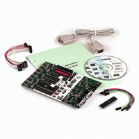
PROGRAMMER AVR STARTER KIT
Manufacturer
Atmel
Series
AVR®r
Type
MCUr
Specifications of ATSTK500
Contents
Board, Cable, CD and Documentation
Data Bus Width
8 bit
Interface Type
RS-232
For Use With/related Products
Atmel AVR Devices
For Use With
ATADAPCAN01 - EXTENSION CAN ADD-ON TO STK500/1
Lead Free Status / RoHS Status
Lead free / RoHS Compliant


5.3.5.3
5.3.6
AVR STK500 User Guide
Oscillator
“Auto” Settings
The STK500 development board uses a programmable oscillator circuit that offers a
wide range of frequencies for the target device.
Since it is not possible to generate an unlimited number of frequencies, the STK500
user interface will calculate the value closest to the value written to the oscillator text
box. The calculated value is then presented in the oscillator text box, overwriting the
previously written number.
When programming multiple devices with the same code, the “Auto” tab offers a power-
ful method of automatically going through a user-defined sequence of commands. The
commands are listed in the order they are executed (if selected). To enable a command,
the appropriate check box should be checked. For example, if only “Program FLASH” is
checked when the “Start” button is pressed, the Flash memory will be programmed with
the hex file specified in the “Program” settings. All commands depend on and use the
settings given in the STK500 user interface.
Figure 5-7. Auto
It is possible to log the command execution to a text file by checking the “Log to file”
check box.
Using AVR Studio
1925C–AVR–3/03
5-7
Related parts for ATSTK500
Image
Part Number
Description
Manufacturer
Datasheet
Request
R

Part Number:
Description:
DEV KIT FOR AVR/AVR32
Manufacturer:
Atmel
Datasheet:

Part Number:
Description:
INTERVAL AND WIPE/WASH WIPER CONTROL IC WITH DELAY
Manufacturer:
ATMEL Corporation
Datasheet:
Part Number:
Description:
Low-Voltage Voice-Switched IC for Hands-Free Operation
Manufacturer:
ATMEL Corporation
Datasheet:
Part Number:
Description:
MONOLITHIC INTEGRATED FEATUREPHONE CIRCUIT
Manufacturer:
ATMEL Corporation
Datasheet:
Part Number:
Description:
AM-FM Receiver IC U4255BM-M
Manufacturer:
ATMEL Corporation
Datasheet:
Part Number:
Description:
Monolithic Integrated Feature Phone Circuit
Manufacturer:
ATMEL Corporation
Datasheet:
Part Number:
Description:
Multistandard Video-IF and Quasi Parallel Sound Processing
Manufacturer:
ATMEL Corporation
Datasheet:
Part Number:
Description:
High-performance EE PLD
Manufacturer:
ATMEL Corporation
Datasheet:
Part Number:
Description:
8-bit Flash Microcontroller
Manufacturer:
ATMEL Corporation
Datasheet:
Part Number:
Description:
2-Wire Serial EEPROM
Manufacturer:
ATMEL Corporation
Datasheet: