ATSTK500 Atmel, ATSTK500 Datasheet
ATSTK500
Specifications of ATSTK500


Related parts for ATSTK500


ATSTK500 Summary of contents
Page 1
STK500 .............................................................................................. User Guide ...
Page 2
...
Page 3
AVR STK500 User Guide Table of Contents Section 1 Introduction ........................................................................................... 1-1 1.1 Starter Kit Features ...................................................................................1-1 1.2 Device Support .........................................................................................1-2 Section 2 Getting Started...................................................................................... 2-1 2.1 Unpacking the System ..............................................................................2-1 2.2 System Requirements...............................................................................2-1 2.3 Quick Start ................................................................................................2-2 2.3.1 Connecting ...
Page 4
Table of Contents ii 1925C–AVR–3/03 3.11.3 Main Power LED...............................................................................3-27 3.11.4 Target Power LED ............................................................................3-27 3.11.5 Status LED .......................................................................................3-27 Section 4 Installing AVR Studio ............................................................................ 4-1 Section 5 Using AVR Studio ................................................................................. 5-1 5.1 Windows Software ....................................................................................5-1 5.2 Starting the Windows ...
Page 5
... Congratulations on your purchase of the AVR Kit. The STK500 is a complete starter kit and development system for the AVR Flash Microcontroller from Atmel Corporation designed to give designers a quick start to develop code on the AVR and for prototyping and testing of new designs. n AVR Studio ® ...
Page 6
... AT90S2343 n ATmega103 n AT90S4414 n ATmega128 Note external target or in STK501, devices do not fit into the sockets of STK500. Support for new AVR devices may be added in new versions of AVR Studio. The latest version of AVR Studio is always available from www.atmel.com. (1) (1) AVR STK500 User Guide ...
Page 7
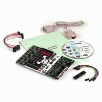
... In-System Programming – (4 pcs) 2-wire cable for UART and DataFlash connections n 9-pin RS-232 cable n DC power cable n Atmel CD-ROM with datasheets and software n AT90S8515-8PC sample microcontroller The minimum hardware and software requirements are: n 486 processor (Pentium ® ...
Page 8
Getting Started 2.3 Quick Start 2-2 1925C–AVR–3/03 The STK500 starter kit is shipped with an AT90S8515-8PC microcontroller in the socket marked SCKT3000D3. The default jumper settings will allow the microcontroller to exe- cute from the clock source and voltage regulator ...
Page 9
Connecting the Hardware 2.3.2 Programming the Target AVR Device AVR STK500 User Guide Figure 2-2. Connection to STK500 To program the AT90S8515, connect the supplied 6-wire cable between the ISP6PIN header and the SPROG3 target ISP header as shown ...
Page 10
Getting Started 2-4 1925C–AVR–3/03 Figure 2-3. AVR Studio STK500 Programming Menu Complete descriptions of using the STK500 interface in AVR Studio are given in Section 5 on page 5-1. AVR STK500 User Guide ...
Page 11
Description of User LEDs AVR STK500 User Guide Figure 3-1. STK500 Components Headers for I/O Ports Switches Header for Switches RS-232 Interface Header DataFlash Interface Header Header for LEDs LEDs Header for Expansion Boards The STK500 starter kit includes ...
Page 12
Hardware Description 3.2 Description of User Switches 3-2 1925C–AVR–3/03 Figure 3-2. Implementation of LEDs and LED Headers VTG 10K LEDn Note: The AVR can source or sink enough current to drive a LED directly. In the STK500 design, a transistor ...
Page 13
Connection of LEDs and Switches 3.4 Port Connectors AVR STK500 User Guide Figure 3-4. Connection of LEDs and Switches to I/O Port Headers Any I/O port of the AVR can be connected to the LEDs and switches using the ...
Page 14
Hardware Description 3-4 1925C–AVR–3/03 Figure 3-6. Pinout of PORTE Header The special functions of this port are: n PE0 - PE2: Table 3-1. PORTE Connection PE0 PE1 PE2 n REF: Analog reference voltage. This pin is connected to the AREF ...
Page 15
Description of User RS-232 Interface AVR STK500 User Guide The STK500 includes two RS-232 ports. One RS-232 port is used for communicating with AVR Studio. The other RS-232 can be used for communicating between the target AVR microcontroller in ...
Page 16
... NB! Not valid: AT45D021 2-Mbit DataFlash is included on the STK500 for data storage. A DataFlash is a high-density Flash memory with SPI serial interface. A detailed datasheet of the DataFlash can be obtained from the Flash memory section of the Atmel CD-ROM or from the Atmel web site. The DataFlash can be connected to the I/O pins of the microcontroller sockets. The 4-pin header marked “ ...
Page 17
AVR STK500 User Guide Figure 3-13. Connection of I/O Pins to DataFlash for AT90S8515 Figure 3-14. Schematic of DataFlash Connections CS S0 SCK SI Hardware Description VTG SCK Voltage AT45D021 Converter DataFlash 5V 3-7 1925C–AVR–3/03 ...
Page 18
Hardware Description 3.7 Target Socket Section 3-8 1925C–AVR–3/03 The programming module consists of the eight sockets in the white area in the middle of the starter kit. In these sockets, the target AVR devices can be inserted for programming and ...
Page 19
ISP Programming AVR STK500 User Guide In-System Programming uses the AVR internal SPI (Serial Peripheral Interface) to download code into the Flash and EEPROM memory of the AVR. ISP programming requires only V , GND, RESET and three signal ...
Page 20
Hardware Description 3-10 1925C–AVR–3/03 Table 3-2. AVR Sockets AVR Devices STK500 Socket AT90S1200 SCKT3300D3 AT90S2313 AT90S2323 SCKT3400D1 AT90S2343 ATtiny12 ATtiny22 ATtiny11 SCKT3400D1 ATtiny28 SCKT3500D- AT90S4414 SCKT3000D3 AT90S8515 ATmega161 AT90S4434 SCKT3100A3 AT90S8535 ATmega16 ATmega163 ATmega323 AT90S2333 SCKT3200A2 AT90S4433 ATmega8 ATtiny15 SCKT3600A1 ...
Page 21
High-voltage Programming AVR STK500 User Guide It is not necessary to remove the 6-wire cable from its ISP position while running a pro- gram in the AVR. The port pins used for ISP programming can be used for other ...
Page 22
Hardware Description 3.7.2.1 Parallel High-voltage Programming 3-12 1925C–AVR–3/03 To use High-voltage Programming, the programming signal must be routed to the AVR I/O pins. The two 10-wire cables supplied with the STK500 can be used to connect the PROG DATA header ...
Page 23
AVR STK500 User Guide Figure 3-18. Jumper Settings for High-voltage Programming VTARGET AREF RESET Jumpers must be Mounted XTAL1 OSCSEL Device- dependent BSEL2 Jumpers (See Below) PJUMP Hardware setup for parallel High-voltage Programming: 1. Switch power off. 2. Place the ...
Page 24
Hardware Description 3.7.2.2 Serial High-voltage Programming 3-14 1925C–AVR–3/03 The 8-pin AVRs have too few pins to use parallel communication during High-voltage Programming. They use serial communication instead. This means that fewer signals have to be routed. Hardware setup for serial ...
Page 25
Jumper Settings AVR STK500 User Guide A master microcontroller and the eight jumpers control the hardware settings of the starter kit. During normal operation these jumpers should be mounted in the default position. To configure the starter kit for ...
Page 26
Hardware Description 3.8.1 Target V Settings, CC VTARGET 3-16 1925C–AVR–3/03 VTARGET controls the supply voltage to the target AVR microcontroller sockets. It can either be controlled from AVR Studio or supplied from an external source. If the VTAR- GET jumper ...
Page 27
Analog Reference Voltage, AREF AVR STK500 User Guide The internal VTARGET has a short circuit protection. If VTARGET is set to be higher than 0.3V and the master microcontroller measures below 0.3V for a duration of ...
Page 28
Hardware Description 3.8.3 Reset Settings, RESET 3-18 1925C–AVR–3/03 Figure 3-24. Internal AREF Connection 10 - 15V VIN PWM Master Wr MCU Rd ADC The AVR Studio-controlled analog reference voltage can also be used as an input to the analog comparator ...
Page 29
AVR STK500 User Guide Figure 3-25. RESET Jumper Options Jumper Mounted AREF RESET XTAL1 On-board RESET Signal Connected (default) Jumper not Mounted AREF RESET XTAL1 On-board RESET Signal Disconnected The STK500 master microcontroller controls the RESET signal to the target ...
Page 30
Hardware Description 3.8.4 Clock Settings, XTAL1 and OSCSEL 3-20 1925C–AVR–3/03 When connected to an external system, there is often an external pull-up resistor con- nected to the reset line. A typical reset connection is shown in Figure 3-27. Figure 3-27. ...
Page 31
AVR STK500 User Guide When the XTAL1 jumper is mounted, the STK500 internal clock system is used as main clock to the target AVR. The internal clock system can either use a crystal in the on-board crystal socket or a ...
Page 32
Hardware Description 3.8.5 BSEL2 Jumper 3.8.6 PJUMP Jumpers 3-22 1925C–AVR–3/03 Figure 3-30. XTAL1 and OSCSEL Connections Oscillator OSCSEL Jumper AVR MASTER Studio MCU The BSEL2 jumper connects the Byte Select 2 signal for High-voltage Programming of ATmega8, ATmega16, ATmega161, ATmega163, ...
Page 33
Expansion Connectors AVR STK500 User Guide STK500 has two expansion connectors, one on each side of the programming module. All AVR I/O ports, programming signals and control signals are routed to the expansion connectors. The expansion connectors allow easy ...
Page 34
Hardware Description 3-24 1925C–AVR–3/03 Figure 3-34. Expansion Connector 0 Pinout GND AUXI0 CT7 CT5 CT3 CT1 NC RST PE1 GND VTG PC7 PC5 PC3 PC1 PA7 PA5 PA3 PA1 GND Figure 3-35. Expansion Connector 1 Pinout GND AUXI1 DATA7 DATA5 ...
Page 35
Signal Descriptions 3.10 Prog Ctrl and Prog Data Headers AVR STK500 User Guide The signals AUXI1, AUXI0, AUXO1, and AUXO0 are intended for future use. Do not connect these signals to your application. The DATA[7:0] and CT[7:1] signals are ...
Page 36
Hardware Description 3.11 Miscellaneous 3.11.1 RESET Push Button 3-26 1925C–AVR–3/03 Figure 3-37. Prog Data Header Pinout The Prog Data signals are used for the data bus when parallel High-voltage Program- ming an AVR device. During ISP programming, DATA5 is used ...
Page 37
PROGRAM Push Button 3.11.3 Main Power LED 3.11.4 Target Power LED 3.11.5 Status LED AVR STK500 User Guide Future versions of AVR Studio may upgrade the master microcontroller on STK500. AVR Studio will then detect old software versions of ...
Page 38
Hardware Description 3-28 1925C–AVR–3/03 AVR STK500 User Guide ...
Page 39
... AVR development. It has an editor, an assembler and a debugger and is front-end for all AVR emulators and the STK500 starter kit. To install AVR Studio, insert the supplied Atmel CD-ROM databook in the computer and navigate to “Products → AVR 8-bit RISC → Software”. Right-click with the mouse on the “ ...
Page 40
Installing AVR Studio 4-2 1925C–AVR–3/03 AVR STK500 User Guide ...
Page 41
... Section 4 on page 4-1. Once installed, AVR Studio can be started by double- clicking on the AVR Studio icon. If default install options are used, the program is located in the Windows “Start menu → Programs → Atmel AVR Tools” folder. Pressing the “AVR” button on the AVR Studio toolbar will start the STK500 user inter- face as shown in Figure 5-1 ...
Page 42
Using AVR Studio 5.3 STK500 User Interface 5.3.1 “Program” Settings 5.3.1.1 Device 5.3.1.2 Programming Mode 5.3.1.3 Flash 5-2 1925C–AVR–3/03 The STK500 user interface includes powerful features for the STK500 development board. The available settings are divided into six groups, each ...
Page 43
EEPROM 5.3.2 “Fuses” Settings AVR STK500 User Guide If the STK500 user interface is opened without a project loaded in AVR Studio, the “Use Current Simulator/Emulator EEPROM Memory” option will be grayed out. When a project is open, this ...
Page 44
Using AVR Studio 5.3.3 “LockBits” Settings 5.3.4 “Advanced” Settings 5.3.4.1 Signature Bytes 5-4 1925C–AVR–3/03 Similar to the “Fuses” tab, the “LockBits” tab shows which lock modes are applicable to the selected device. All lock bits are accessible in both ISP ...
Page 45
Oscillator Calibration Byte 5.3.4.3 Reading Oscillator Calibration Byte 5.3.4.4 Writing Oscillator Calibration Byte 5.3.5 “Board” Settings AVR STK500 User Guide Figure 5-5. Advanced The oscillator calibration byte is written to the device during manufacturing, and cannot be erased or ...
Page 46
Using AVR Studio 5.3.5.1 VTARGET 5.3.5.2 AREF 5-6 1925C–AVR–3/03 Figure 5-6. Board VTARGET controls the operating voltage for the target board. Through the use of the slide bar or the text box, this voltage can be regulated between 0 and ...
Page 47
Oscillator 5.3.6 “Auto” Settings AVR STK500 User Guide The STK500 development board uses a programmable oscillator circuit that offers a wide range of frequencies for the target device. Since it is not possible to generate an unlimited number of ...
Page 48
Using AVR Studio 5.3.6.1 Setting Up the System for Auto-programming 5.3.6.2 Logging the Auto-programming to a File 5.3.7 History Window 5-8 1925C–AVR–3/03 Click on the check boxes for the commands that you want the STK500 user interface to perform. A ...
Page 49
Command Line Software 5.5 Parameters AVR STK500 User Guide The DOS command line version of the STK500 software is useful for programming STK500 from external editors or for use in production programmers. Simple batch files can be made for ...
Page 50
Using AVR Studio 5-10 1925C–AVR–3/03 f Set fuse bytes. “value” 16-bit hex. value describing the settings for the upper and lower fuse. E Set extended fuse byte. “value” 8-bit hex. value describing the extend fuse settings. ...
Page 51
AVR STK500 User Guide In-System Programming of an External Target System The STK500 can be used as a programmer to program AVR devices in other applica- tions. There are two different ISP connector pinouts available: a 6-pin and a 10-pin ...
Page 52
In-System Programming of an External Target System 6-2 1925C–AVR–3/03 AVR STK500 User Guide ...
Page 53
AVR STK500 User Guide Troubleshooting Guide Table 7-1. Troubleshooting Guide Problem Reason The red power LED is not on. The DC power cable is not connected. Wrong power supply is used. The power switch is off. The preprogrammed There is ...
Page 54
Troubleshooting Guide 7-2 1925C–AVR–3/03 Table 7-1. Troubleshooting Guide (Continued) Problem Reason The AVR device cannot be Reset disable fuse is set. programmed (continued). Programming too fast External pull-up resistor on reset line too low. AVR Studio does not detect Serial ...
Page 55
... AVR STK500 User Guide For technical support, please contact avr@atmel.com. When requesting technical sup- port for STK500, please include the following information: n Version number of AVR Studio. This can be found in the AVR Studio menu, “Help → About” processor type and speed ...
Page 56
Technical Support 8-2 1925C–AVR–3/03 AVR STK500 User Guide ...
Page 57
Using LEDs and Switches AVR STK500 User Guide Connect PORTB to LEDS and PORTD to SWITCHES. LEDs will operate differently depending on what switch is pressed. Tip: Copy the code from this document into AVR Studio. ;***** STK500 LEDS ...
Page 58
Example Applications 9-2 1925C–AVR–3/03 dec Temp sbis PIND,0x02 ror Temp sbis PIND,0x03 rol Temp sbis PIND,0x04 com Temp sbis PIND,0x05 neg Temp sbis PIND,0x06 swap Temp ;**** Now wait a while to make LED changes visible. DLY: dec Delay brne ...
Page 59
AVR STK500 User Guide Figure 10-1. STK500 Block Diagram SPARE RS232 UART SPARE CONTROL RS232 UART CTRL SELF- PROG. SYSTEM RESET BUTTON PROGRAM BUTTON CONTROL MCU HW REVISION STATUS LED AUX INTERFACE POWER TO CONTROL SECTION POWER POWER POWER BUTTON ...
Page 60
Appendix A 10-2 1925C–AVR–3/03 AVR STK500 User Guide ...
Page 61
... No licenses to patents or other intellectual property of Atmel are granted by the Company in connection with the sale of Atmel products, expressly or by implication. Atmel’s products are not authorized for use as critical components in life support devices or systems. ...