ATSTK500 Atmel, ATSTK500 Datasheet - Page 49
ATSTK500
Manufacturer Part Number
ATSTK500
Description
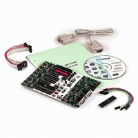
PROGRAMMER AVR STARTER KIT
Manufacturer
Atmel
Series
AVR®r
Type
MCUr
Specifications of ATSTK500
Contents
Board, Cable, CD and Documentation
Data Bus Width
8 bit
Interface Type
RS-232
For Use With/related Products
Atmel AVR Devices
For Use With
ATADAPCAN01 - EXTENSION CAN ADD-ON TO STK500/1
Lead Free Status / RoHS Status
Lead free / RoHS Compliant


5.4
5.5
AVR STK500 User Guide
Command Line
Software
Parameters
The DOS command line version of the STK500 software is useful for programming
STK500 from external editors or for use in production programmers. Simple batch files
can be made for automatic programming. Type “STK500 -?” for help.
The program returns ERRORCODE 0 if the operation was successful, and ERROR-
CODE 1 if the operation failed.
Command Line Switches:
d
m
if
ie
of
oe
s
O
Sf
Se
e
p
r
v
l
L
y
[-d device name] [-m s|p] [-if infile] [-ie infile] [-of outfile]
[-oe outfile] [-s] [-O] [-Sf addr] [-Seaddr] [-e] [-p f|e|b]
[-r f|e|b] [-v f|e|b] [-l value] [-L value] [-y] [-f value] [-E value]
[-F value] [-G value] [-q] [-x value] [-af start,stop] [-ae start,stop]
[-c port] [-ut value] [-ua value] [-wt] [-wa] [-b h|s] [-! freq] [-t]
[-g] [-z] [-h|?]
Device name. Must be applied when programming the device. See list below.
Select programming mode; serial (s) or parallel/High-voltage (p).
Serial programming mode is the default, and is used if this parameter not
applied.
Name of FLASH input file. Required for programming or verification of the FLASH
memory. The file format is Intel Extended HEX.
Name of EEPROM input file. Required for programming or verification of the
EEPROM memory. The file format is Intel Extended HEX.
Name of flash output file. Required for readout of the FLASH memory. The file
format is Intel Extended HEX.
Name of EEPROM output file. Required for readout of the EEPROM memory. The
file format is Intel Extended HEX.
Read signature bytes.
Read oscillator calibration byte.
Write oscillator call. byte to FLASH memory. “addr” is byte address
Write oscillator call. byte to EEPROM memory. “addr” is byte address
Erase device. If applied with another programming parameter, the device will be
erased before any other programming takes place.
Program device; FLASH (f), EEPROM (e) or both (b). Corresponding input files
are required.
Read out device; FLASH (f), EEPROM (e) or both (b). Corresponding output files
are required
Verify device; FLASH (f), EEPROM (e) or both (b). Can be used with -p or stand
alone. Corresponding input files are required.
Set lock byte. “value' is an 8-bit hex. value.
Verify lock byte. “value” is an 8-bit hex. value to verify against.
Read back lock byte.
Using AVR Studio
1925C–AVR–3/03
5-9
Related parts for ATSTK500
Image
Part Number
Description
Manufacturer
Datasheet
Request
R

Part Number:
Description:
DEV KIT FOR AVR/AVR32
Manufacturer:
Atmel
Datasheet:

Part Number:
Description:
INTERVAL AND WIPE/WASH WIPER CONTROL IC WITH DELAY
Manufacturer:
ATMEL Corporation
Datasheet:
Part Number:
Description:
Low-Voltage Voice-Switched IC for Hands-Free Operation
Manufacturer:
ATMEL Corporation
Datasheet:
Part Number:
Description:
MONOLITHIC INTEGRATED FEATUREPHONE CIRCUIT
Manufacturer:
ATMEL Corporation
Datasheet:
Part Number:
Description:
AM-FM Receiver IC U4255BM-M
Manufacturer:
ATMEL Corporation
Datasheet:
Part Number:
Description:
Monolithic Integrated Feature Phone Circuit
Manufacturer:
ATMEL Corporation
Datasheet:
Part Number:
Description:
Multistandard Video-IF and Quasi Parallel Sound Processing
Manufacturer:
ATMEL Corporation
Datasheet:
Part Number:
Description:
High-performance EE PLD
Manufacturer:
ATMEL Corporation
Datasheet:
Part Number:
Description:
8-bit Flash Microcontroller
Manufacturer:
ATMEL Corporation
Datasheet:
Part Number:
Description:
2-Wire Serial EEPROM
Manufacturer:
ATMEL Corporation
Datasheet: