ATSTK500 Atmel, ATSTK500 Datasheet - Page 14
ATSTK500
Manufacturer Part Number
ATSTK500
Description
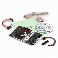
PROGRAMMER AVR STARTER KIT
Manufacturer
Atmel
Series
AVR®r
Type
MCUr
Specifications of ATSTK500
Contents
Board, Cable, CD and Documentation
Data Bus Width
8 bit
Interface Type
RS-232
For Use With/related Products
Atmel AVR Devices
For Use With
ATADAPCAN01 - EXTENSION CAN ADD-ON TO STK500/1
Lead Free Status / RoHS Status
Lead free / RoHS Compliant


1925C–AVR–3/03
Hardware Description
3-4
Figure 3-6. Pinout of PORTE Header
The special functions of this port are:
n PE0 - PE2:
Table 3-1. PORTE Connection
n REF: Analog reference voltage. This pin is connected to the AREF pin on devices
n XT1: XTAL 1 pin. The internal main clock signal to all sockets. If the XTAL1 jumper is
n XT2: XTAL 2 pin. If the XTAL1 jumper is disconnected, this pin can be used for
The headers for the LEDs and switches use the same pinout as the I/O port headers.
The pinout of the switch header is explained in Figure 3-7 and the pinout for the LED
header is explained in Figure 3-8. The square marking indicates pin 1.
Figure 3-7. Pinout of the Switch Header
Figure 3-8. Pinout of the LED Header
PE0
PE1
PE2
having a separate analog reference pin.
disconnected, this pin can be used as external clock signal.
external crystal with the XT1 pin.
LED0
LED2
LED4
LED6
GND
GND
SW0
SW2
SW4
SW6
GND
REF
PE0
PE2
XT1
PORTE/AUX
PE0/ICP/INT2
SWITCHES
ATmega161
PE2/OC1B
PE1/ALE
LEDS
1 2
1 2
1 2
PE1
RST
GND
XT2
VTG
SW1
SW3
SW5
SW7
VTG
LED1
LED3
LED5
LED7
VTG
AT90S4414/AT90S8515
AVR STK500 User Guide
OC1B
ALE
ICP
Related parts for ATSTK500
Image
Part Number
Description
Manufacturer
Datasheet
Request
R

Part Number:
Description:
DEV KIT FOR AVR/AVR32
Manufacturer:
Atmel
Datasheet:

Part Number:
Description:
INTERVAL AND WIPE/WASH WIPER CONTROL IC WITH DELAY
Manufacturer:
ATMEL Corporation
Datasheet:
Part Number:
Description:
Low-Voltage Voice-Switched IC for Hands-Free Operation
Manufacturer:
ATMEL Corporation
Datasheet:
Part Number:
Description:
MONOLITHIC INTEGRATED FEATUREPHONE CIRCUIT
Manufacturer:
ATMEL Corporation
Datasheet:
Part Number:
Description:
AM-FM Receiver IC U4255BM-M
Manufacturer:
ATMEL Corporation
Datasheet:
Part Number:
Description:
Monolithic Integrated Feature Phone Circuit
Manufacturer:
ATMEL Corporation
Datasheet:
Part Number:
Description:
Multistandard Video-IF and Quasi Parallel Sound Processing
Manufacturer:
ATMEL Corporation
Datasheet:
Part Number:
Description:
High-performance EE PLD
Manufacturer:
ATMEL Corporation
Datasheet:
Part Number:
Description:
8-bit Flash Microcontroller
Manufacturer:
ATMEL Corporation
Datasheet:
Part Number:
Description:
2-Wire Serial EEPROM
Manufacturer:
ATMEL Corporation
Datasheet: