ATSTK500 Atmel, ATSTK500 Datasheet - Page 30
ATSTK500
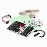
Manufacturer Part Number
ATSTK500
Description
PROGRAMMER AVR STARTER KIT
Manufacturer
Atmel
Series
AVR®r
Type
MCUr
Specifications of ATSTK500
Contents
Board, Cable, CD and Documentation
Data Bus Width
8 bit
Interface Type
RS-232
For Use With/related Products
Atmel AVR Devices
For Use With
ATADAPCAN01 - EXTENSION CAN ADD-ON TO STK500/1
Lead Free Status / RoHS Status
Lead free / RoHS Compliant


1925C–AVR–3/03
Hardware Description
3.8.4
3-20
Clock Settings,
XTAL1 and OSCSEL
When connected to an external system, there is often an external pull-up resistor con-
nected to the reset line. A typical reset connection is shown in Figure 3-27.
Figure 3-27. External Reset Connection
If the external pull-up resistor is too low (<4.7 kΩ), STK500 will not be able to pull the
RESET line low.
STK500 includes several clock options for the target AVR. Setting the jumpers XTAL1
and OSCSEL controls the clock selections. OSCSEL determines what signal to route to
the XTAL1 pin of the AVR.
When the XTAL1 jumper is connected, the STK500 internal clock system is used as
main clock to the target AVR. When XTAL1 jumper is not mounted, the internal clock
system is disconnected. This allows external clock signals or crystals to be used as tar-
get clock source for the AVR. Figure 3-28 illustrates the XTAL1 jumper option.
Figure 3-28. XTAL1 Jumper Options
When the XTAL1 jumper is not mounted, an external clock source or crystal can be con-
nected to the PORTE header. This is shown in Figure 3-30.
Jumper Mounted
On-board XTAL1 Signal Connected (Default)
Jumper not Mounted
On-board XTAL1 Signal Disconnected
OSCSEL
OSCSEL
RESET
RESET
XTAL1
XTAL1
AREF
AREF
R (4.7 kohm)
C (10 nF)
RESET
AVR STK500 User Guide
Related parts for ATSTK500
Image
Part Number
Description
Manufacturer
Datasheet
Request
R

Part Number:
Description:
DEV KIT FOR AVR/AVR32
Manufacturer:
Atmel
Datasheet:

Part Number:
Description:
INTERVAL AND WIPE/WASH WIPER CONTROL IC WITH DELAY
Manufacturer:
ATMEL Corporation
Datasheet:
Part Number:
Description:
Low-Voltage Voice-Switched IC for Hands-Free Operation
Manufacturer:
ATMEL Corporation
Datasheet:
Part Number:
Description:
MONOLITHIC INTEGRATED FEATUREPHONE CIRCUIT
Manufacturer:
ATMEL Corporation
Datasheet:
Part Number:
Description:
AM-FM Receiver IC U4255BM-M
Manufacturer:
ATMEL Corporation
Datasheet:
Part Number:
Description:
Monolithic Integrated Feature Phone Circuit
Manufacturer:
ATMEL Corporation
Datasheet:
Part Number:
Description:
Multistandard Video-IF and Quasi Parallel Sound Processing
Manufacturer:
ATMEL Corporation
Datasheet:
Part Number:
Description:
High-performance EE PLD
Manufacturer:
ATMEL Corporation
Datasheet:
Part Number:
Description:
8-bit Flash Microcontroller
Manufacturer:
ATMEL Corporation
Datasheet:
Part Number:
Description:
2-Wire Serial EEPROM
Manufacturer:
ATMEL Corporation
Datasheet: