ATSTK500 Atmel, ATSTK500 Datasheet - Page 31
ATSTK500
Manufacturer Part Number
ATSTK500
Description
PROGRAMMER AVR STARTER KIT
Manufacturer
Atmel
Series
AVR®r
Type
MCUr
Specifications of ATSTK500
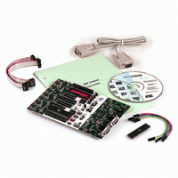
Contents
Board, Cable, CD and Documentation
Data Bus Width
8 bit
Interface Type
RS-232
For Use With/related Products
Atmel AVR Devices
For Use With
ATADAPCAN01 - EXTENSION CAN ADD-ON TO STK500/1
Lead Free Status / RoHS Status
Lead free / RoHS Compliant


AVR STK500 User Guide
When the XTAL1 jumper is mounted, the STK500 internal clock system is used as main
clock to the target AVR. The internal clock system can either use a crystal in the
on-board crystal socket or a software-generated clock from the master microcontroller.
The frequency of the software-generated clock can be set from 0 to 3.68 MHz. The
default value is 3.68 MHz. Section 5.3.5.3 on page 5-7 explains how to set the clock fre-
quency from AVR Studio.
When using the STK500 software-generated clock system as main clock, the target
AVR microcontroller fuses should be configured for “external clock” as clock source.
This gives shortest start-up time for the microcontroller. For details of start-up time, see
the datasheet for the AVR microcontroller. For an explanation of clock source fuses con-
figuration, see Section 5.3.2 on page 5-3. Not all AVR devices have fuses for selection
between using a crystal or oscillator as clock source.
The internal clock system is selected with the OSCSEL jumper. Figure 3-29 shows the
jumper options for OSCSEL.
The on-board oscillator will work with ceramic resonators or crystals between
2 - 20 MHz (AT-cut, fundamental and parallel resonant crystals).
Figure 3-29. OSCSEL Jumper Options
When programming AVR in High-voltage Programming mode, OSCSEL should be
mounted on pins 1 and 2 to give the master microcontroller control of the target clock.
This is explained in detail in Section 3.7.2 on page 3-11.
Note:
On-board XTAL1 signal disconnected
On-board software clock signal connected (default)
On-board crystal signal connected
Jumper not mounted
Jumper mounted on pins 1 and 2
Jumper mounted on pins 2 and 3
In a real application with only one AVR connected to the crystal, there is no
need for an external oscillator circuit. The STK500 has eight different AVR
sockets connected to the same clock system. The long signal lines in this
system makes it difficult to drive a crystal with the On-chip Oscillators on the
AVR. The oscillator on STK500 is designed to operate on all target voltages
from 1.8 to 6.0V.
OSCSEL
OSCSEL
OSCSEL
XTAL1
XTAL1
XTAL1
Hardware Description
1925C–AVR–3/03
3-21
Related parts for ATSTK500
Image
Part Number
Description
Manufacturer
Datasheet
Request
R

Part Number:
Description:
DEV KIT FOR AVR/AVR32
Manufacturer:
Atmel
Datasheet:

Part Number:
Description:
INTERVAL AND WIPE/WASH WIPER CONTROL IC WITH DELAY
Manufacturer:
ATMEL Corporation
Datasheet:
Part Number:
Description:
Low-Voltage Voice-Switched IC for Hands-Free Operation
Manufacturer:
ATMEL Corporation
Datasheet:
Part Number:
Description:
MONOLITHIC INTEGRATED FEATUREPHONE CIRCUIT
Manufacturer:
ATMEL Corporation
Datasheet:
Part Number:
Description:
AM-FM Receiver IC U4255BM-M
Manufacturer:
ATMEL Corporation
Datasheet:
Part Number:
Description:
Monolithic Integrated Feature Phone Circuit
Manufacturer:
ATMEL Corporation
Datasheet:
Part Number:
Description:
Multistandard Video-IF and Quasi Parallel Sound Processing
Manufacturer:
ATMEL Corporation
Datasheet:
Part Number:
Description:
High-performance EE PLD
Manufacturer:
ATMEL Corporation
Datasheet:
Part Number:
Description:
8-bit Flash Microcontroller
Manufacturer:
ATMEL Corporation
Datasheet:
Part Number:
Description:
2-Wire Serial EEPROM
Manufacturer:
ATMEL Corporation
Datasheet: