EVL6566A-75WES4 STMicroelectronics, EVL6566A-75WES4 Datasheet - Page 9
EVL6566A-75WES4
Manufacturer Part Number
EVL6566A-75WES4
Description
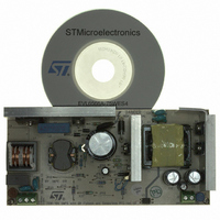
BOARD DEMO FOR L6563/LL6566A
Manufacturer
STMicroelectronics
Type
Power Factor Correctionr
Specifications of EVL6566A-75WES4
Main Purpose
AC/DC, Primary and Secondary Side with PFC
Outputs And Type
1, Isolated
Power - Output
75W
Voltage - Output
19V
Current - Output
4A
Voltage - Input
90 ~ 264VAC
Regulator Topology
Flyback
Board Type
Fully Populated
Utilized Ic / Part
L6563, L6566A, TSM1014
Input Voltage
90 V to 264 V
Output Voltage
19 V
Dimensions
78 mm x 170 mm
Product
Power Management Modules
Lead Free Status / RoHS Status
Lead free / RoHS Compliant
Frequency - Switching
-
Lead Free Status / Rohs Status
Lead free / RoHS Compliant
For Use With/related Products
L6563S, L6566A
Other names
497-8834
Available stocks
Company
Part Number
Manufacturer
Quantity
Price


AN2941
Main characteristics and circuit description
The output rectifiers are two dual center tap Schottky diodes (D7 and D5) in parallel. They
have been selected according to the maximum reverse voltage, forward voltage drop and
power dissipation. The snubber made up of R14, R66 and C8 damps the oscillation
produced by the diode capacitance and the leakage inductance. A small LC filter has been
added on the output, filtering the high frequency ripple.
D17, R75÷R78, Q10 and Q15 implement an output voltage “fast discharge” circuit,
discharging quickly the output capacitors when the converter is turned off. It has been
implemented to quickly decrease the residual output voltage after the converter is turned off
at no load.
Startup sequence
The circuit is designed so that at startup the flyback starts first, then it turns on the PFC
stage controlling the L6563S via the Vcc_PFC pin. Therefore, the flyback stage is designed
to manage at startup the full output power over the entire input voltage range because it
must guarantee the regulation of the output voltage even during load transitions when the
load is increasing but the PFC is still not yet delivering the nominal output voltage. Of course
this condition can be maintained only for a short time, typically tens of milliseconds, because
the flyback is not designed to sustain this condition from a thermal point of view. The flyback
controller L6566A pin #1 (HV) is directly connected to the bulk capacitor. At startup, an
internal high voltage current source charges C32 and C33 until the L6566A turn-on voltage
threshold is reached, then the high voltage current source is automatically switched off. As
the IC starts switching it is initially supplied by C32 and C33, then the transformer auxiliary
winding (pins 8-9) provide the voltage to power the IC. Afterwards, according to the load
level monitored by the COMP pin, the L6566A activates the L6563S powering it via the
Vcc_PFC pin.
Because the L6566A integrated HV startup circuit is turned off and therefore not dissipative
during normal operation, it contributes significantly to reducing power consumption when
the power supply operates at light load which in turn contributes significantly in meeting
worldwide standby standards currently required.
Brownout protection
Brownout protection prevents the circuit from working with abnormal mains levels. It can be
easily achieved using pin #16 (AC_OK) of the L6566A. D6, Q3, C23, R7, R12, R26, R62
and R64 implement a circuit sensing the mains voltage peak value and feed it into L6566A
pin #16. An internal comparator then enables the IC operations if the mains level is correct,
within the nominal limits. If the input voltage is below 90 Vac the startup of the circuit is
inhibited, while the turn-off voltage has been set at the voltage reached by the bulk capacitor
after the hold-up time. The internal comparator has in fact a hysteresis allowing the L6566A
turn-on and turn-off voltage to be set independently. Sensing the mains voltage before the
input rectifier is a less dissipative solution with respect to sensing the bulk voltage. In
addition it allows faster restart because there is no need to wait for the bulk capacitor to
discharge.
The L6563S has a similar protection on the RUN pin (#10) but in this schematic it is not used
because in this architecture it acts as slave, therefore the main controls are managed by the
flyback stage.
Doc ID 15447 Rev 3
9/37
Related parts for EVL6566A-75WES4
Image
Part Number
Description
Manufacturer
Datasheet
Request
R

Part Number:
Description:
BOARD EVAL FOR L6566A
Manufacturer:
STMicroelectronics
Datasheet:

Part Number:
Description:
STMicroelectronics [RIPPLE-CARRY BINARY COUNTER/DIVIDERS]
Manufacturer:
STMicroelectronics
Datasheet:
Part Number:
Description:
STMicroelectronics [LIQUID-CRYSTAL DISPLAY DRIVERS]
Manufacturer:
STMicroelectronics
Datasheet:

Part Number:
Description:
BOARD EVAL FOR MEMS SENSORS
Manufacturer:
STMicroelectronics
Datasheet:
Part Number:
Description:
NPN TRANSISTOR POWER MODULE
Manufacturer:
STMicroelectronics
Datasheet:
Part Number:
Description:
TURBOSWITCH ULTRA-FAST HIGH VOLTAGE DIODE
Manufacturer:
STMicroelectronics
Datasheet:
Part Number:
Description:
Manufacturer:
STMicroelectronics
Datasheet:
Part Number:
Description:
DIODE / SCR MODULE
Manufacturer:
STMicroelectronics
Datasheet:
Part Number:
Description:
DIODE / SCR MODULE
Manufacturer:
STMicroelectronics
Datasheet:
Part Number:
Description:
Search -----> STE16N100
Manufacturer:
STMicroelectronics
Datasheet:
Part Number:
Description:
Search ---> STE53NA50
Manufacturer:
STMicroelectronics
Datasheet:
Part Number:
Description:
NPN Transistor Power Module
Manufacturer:
STMicroelectronics
Datasheet: