EVL6566A-75WES4 STMicroelectronics, EVL6566A-75WES4 Datasheet - Page 8
EVL6566A-75WES4
Manufacturer Part Number
EVL6566A-75WES4
Description
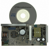
BOARD DEMO FOR L6563/LL6566A
Manufacturer
STMicroelectronics
Type
Power Factor Correctionr
Specifications of EVL6566A-75WES4
Main Purpose
AC/DC, Primary and Secondary Side with PFC
Outputs And Type
1, Isolated
Power - Output
75W
Voltage - Output
19V
Current - Output
4A
Voltage - Input
90 ~ 264VAC
Regulator Topology
Flyback
Board Type
Fully Populated
Utilized Ic / Part
L6563, L6566A, TSM1014
Input Voltage
90 V to 264 V
Output Voltage
19 V
Dimensions
78 mm x 170 mm
Product
Power Management Modules
Lead Free Status / RoHS Status
Lead free / RoHS Compliant
Frequency - Switching
-
Lead Free Status / Rohs Status
Lead free / RoHS Compliant
For Use With/related Products
L6563S, L6566A
Other names
497-8834
Available stocks
Company
Part Number
Manufacturer
Quantity
Price


Main characteristics and circuit description
8/37
During light-load operation the PFC controller is stopped by the PWM controller, so the
MOSFET doesn’t switch and there is no reflected voltage on the auxiliary winding. C
and C
networks do not dissipate.
The divider R3, R5, R11, R10 and R19, directly connected to the output voltage, is
dedicated to protect the circuit in case of output overvoltage or open loop via pin PFC_OK
(#7).
Tracking boost option
To maximize overall efficiency the PFC makes use of the “Tracking Boost Option”. With this
function implemented the PFC DC output voltage changes proportionally to the mains
voltage. The L6563S can implement this function by just adding a resistor (R30) connected
to the dedicated pin (TBO, #6). Furthermore, the tracking boost option allows the use of a
smaller (and cheaper) inductor. In this case a 400 µH inductor has been used while, with a
fixed output voltage PFC working at similar operating frequency, a 700 µH inductor is
needed.
Fast voltage feed-forward
The voltage on the L6563S Vff pin (#5) is the peak value of the voltage on MULT pin (#3).
The RC network (R34, C21) connected to Vff completes the peak-holding circuit. This signal
is necessary to derive information from the RMS input voltage to compensate the loop gain
that is mains voltage dependent.
Generally speaking, if the time constant is too small, the voltage generated is affected by a
considerable amount of ripple at twice the mains frequency, causing distortion of the current
reference (resulting in high THD and poor PF). If the time constant is too large there is a
considerable delay in setting the right amount of feed-forward, resulting in excessive
overshoot or undershoot of the pre-regulator's output voltage in response to large line
voltage changes.
To overcome this issue, the L6563S implements the new fast Vff function. As soon as the
voltage on the Vff pin decreases from a set threshold (40 mV typically), a mains dip is
assumed and an internal switch rapidly discharges the Vff capacitor via a 10 kΩ resistor.
Thanks to this feature it is possible to set an RC circuit with a long time constant, assuring a
low THD, and keeping a fast response to the mains dip.
Flyback power stage
The downstream converter, acting as the master stage, implements the ST L6566A (U6), a
new dedicated current mode controller. The IC operates in quasi-resonant mode detecting
the transformer demagnetization by pin ZCD (#11). R42 on pin OSC (#13) sets the
maximum switching frequency at about 125 kHz. This value has been chosen to limit the
switching losses.
Due to the fact that the maximum switching frequency is imposed, the converter operates in
discontinuous conduction mode during light-load operation. Thanks to the L6566A valley
skipping function, even in this condition, the flyback operates in valley switching, reducing
switching losses. The MOSFET is a standard 800 V, STF7NM80, housed in the TO-220FP
package, needing just a small heat sink. The transformer is layer type, using a standard
ferrite size EER35. The transformer, designed according to EN60950, is manufactured by
TDK. The flyback reflected voltage is ~130 V, providing enough room for the leakage
inductance voltage spike with still margin for reliability of the MOSFET. The rectifier D8 and
the transil D4 clamp the peak of the leakage inductance voltage spike at MOSFET turn-off.
3
are no longer charged and discharged and so both the multiplier and the feedback
Doc ID 15447 Rev 3
AN2941
1
, C
2
Related parts for EVL6566A-75WES4
Image
Part Number
Description
Manufacturer
Datasheet
Request
R

Part Number:
Description:
BOARD EVAL FOR L6566A
Manufacturer:
STMicroelectronics
Datasheet:

Part Number:
Description:
STMicroelectronics [RIPPLE-CARRY BINARY COUNTER/DIVIDERS]
Manufacturer:
STMicroelectronics
Datasheet:
Part Number:
Description:
STMicroelectronics [LIQUID-CRYSTAL DISPLAY DRIVERS]
Manufacturer:
STMicroelectronics
Datasheet:

Part Number:
Description:
BOARD EVAL FOR MEMS SENSORS
Manufacturer:
STMicroelectronics
Datasheet:
Part Number:
Description:
NPN TRANSISTOR POWER MODULE
Manufacturer:
STMicroelectronics
Datasheet:
Part Number:
Description:
TURBOSWITCH ULTRA-FAST HIGH VOLTAGE DIODE
Manufacturer:
STMicroelectronics
Datasheet:
Part Number:
Description:
Manufacturer:
STMicroelectronics
Datasheet:
Part Number:
Description:
DIODE / SCR MODULE
Manufacturer:
STMicroelectronics
Datasheet:
Part Number:
Description:
DIODE / SCR MODULE
Manufacturer:
STMicroelectronics
Datasheet:
Part Number:
Description:
Search -----> STE16N100
Manufacturer:
STMicroelectronics
Datasheet:
Part Number:
Description:
Search ---> STE53NA50
Manufacturer:
STMicroelectronics
Datasheet:
Part Number:
Description:
NPN Transistor Power Module
Manufacturer:
STMicroelectronics
Datasheet: