EVL6566A-75WES4 STMicroelectronics, EVL6566A-75WES4 Datasheet - Page 10
EVL6566A-75WES4
Manufacturer Part Number
EVL6566A-75WES4
Description
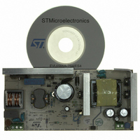
BOARD DEMO FOR L6563/LL6566A
Manufacturer
STMicroelectronics
Type
Power Factor Correctionr
Specifications of EVL6566A-75WES4
Main Purpose
AC/DC, Primary and Secondary Side with PFC
Outputs And Type
1, Isolated
Power - Output
75W
Voltage - Output
19V
Current - Output
4A
Voltage - Input
90 ~ 264VAC
Regulator Topology
Flyback
Board Type
Fully Populated
Utilized Ic / Part
L6563, L6566A, TSM1014
Input Voltage
90 V to 264 V
Output Voltage
19 V
Dimensions
78 mm x 170 mm
Product
Power Management Modules
Lead Free Status / RoHS Status
Lead free / RoHS Compliant
Frequency - Switching
-
Lead Free Status / Rohs Status
Lead free / RoHS Compliant
For Use With/related Products
L6563S, L6566A
Other names
497-8834
Available stocks
Company
Part Number
Manufacturer
Quantity
Price


Main characteristics and circuit description
10/37
Output voltage feedback loop
The output regulation is done by means of two control loops, a voltage and a current loop
working alternatively. A dedicated control IC, the TSM1014 (U5), has been used. It
integrates two operational amplifiers (used as error amplifiers) and a precise voltage
reference. The output signal of the error amplifiers drives an optocoupler SFH617A-4 (U3)
to get the required insulation of the secondary side and modulating the voltage on COMP
pin (#9) of the L6566A.
L6566A current mode control and voltage feed-forward function
R52 and R53 sense the Q5 MOSFET current of the flyback and the signal is fed into pin #7
(CS) connected to the PWM comparator. This signal is compared with the COMP (pin #9)
signal which is coming from the optocoupler.
The maximum power that the converter can deliver is set by a comparator limiting the peak
of the primary current, comparing the CS and an internal threshold (V
signal exceeds the threshold, the comparator limits the MOSFET duty cycle, hence the
output power is also limited.
Because the maximum transferable power depends on both the primary peak current and
the input voltage, in order to keep almost constant the overload set point that would change
according to flyback input voltage, the L6566A implements a voltage feed-forward function
via a dedicated pin. Hence, V
bulk voltage by a resistor divider. A higher voltage causes a smaller V
maximum power can be kept almost constant at any input voltage.
L6566A short-circuit protection
In case of short-circuit, an internal comparator senses the COMP pin after the soft-start at
which time the COMP pin goes high, activating an internal current source that restarts
charging the soft-start capacitor from the initial 2 V level. If the voltage on this pin reaches
5 V, the L6566A stops the operation and enters in the “hiccup mode”. The L6566A restarts
with a startup sequence when the Vcc voltage drops below the V
Because of the long time needed by the V
load operation increases, thus decreasing the power dissipation and the stress of the power
components. This sequence is repeated until the short is removed following which normal
operation of the converter is automatically resumed.
Another comparator, whose threshold is 1.5 V and dedicated to protecting the circuit in case
of transformer saturation or secondary diodes short, is also provided. If the voltage on the
CS pin (#7) exceeds this threshold two consecutive times, the IC immediately shuts down
and latches off. This is intended to prevent spurious activation of the protection in case of
temporary disturbances, for example during the immunity tests. Even in this case the IC
operation is resumed as soon as the V
mode operation is still obtained, avoiding consequent failures due to overheating of the
power components.
Overvoltage protection
Pin #11 (ZCD) is connected to the auxiliary winding by a resistor divider. It implements the
OVP against feedback network failures. When the ZCD pin voltage exceeds 5 V the IC is
shut down. This protection can be set as latched or auto-restart by the user with no
additional components. On the board it is set as latched, therefore operations can resume
after a mains recycling.
CSX
Doc ID 15447 Rev 3
is modulated by the voltage on pin #15 (V
CC
voltage drops below 5 V. In this way a hiccup
CC
capacitor to drop to 5 V, the duration of the no-
CCrestart
CS,MAX
CSX
). If the current
level (5 V).
FF
so that the
) sensing the
AN2941
Related parts for EVL6566A-75WES4
Image
Part Number
Description
Manufacturer
Datasheet
Request
R

Part Number:
Description:
BOARD EVAL FOR L6566A
Manufacturer:
STMicroelectronics
Datasheet:

Part Number:
Description:
STMicroelectronics [RIPPLE-CARRY BINARY COUNTER/DIVIDERS]
Manufacturer:
STMicroelectronics
Datasheet:
Part Number:
Description:
STMicroelectronics [LIQUID-CRYSTAL DISPLAY DRIVERS]
Manufacturer:
STMicroelectronics
Datasheet:

Part Number:
Description:
BOARD EVAL FOR MEMS SENSORS
Manufacturer:
STMicroelectronics
Datasheet:
Part Number:
Description:
NPN TRANSISTOR POWER MODULE
Manufacturer:
STMicroelectronics
Datasheet:
Part Number:
Description:
TURBOSWITCH ULTRA-FAST HIGH VOLTAGE DIODE
Manufacturer:
STMicroelectronics
Datasheet:
Part Number:
Description:
Manufacturer:
STMicroelectronics
Datasheet:
Part Number:
Description:
DIODE / SCR MODULE
Manufacturer:
STMicroelectronics
Datasheet:
Part Number:
Description:
DIODE / SCR MODULE
Manufacturer:
STMicroelectronics
Datasheet:
Part Number:
Description:
Search -----> STE16N100
Manufacturer:
STMicroelectronics
Datasheet:
Part Number:
Description:
Search ---> STE53NA50
Manufacturer:
STMicroelectronics
Datasheet:
Part Number:
Description:
NPN Transistor Power Module
Manufacturer:
STMicroelectronics
Datasheet: