EVL6566A-75WES4 STMicroelectronics, EVL6566A-75WES4 Datasheet - Page 18
EVL6566A-75WES4
Manufacturer Part Number
EVL6566A-75WES4
Description
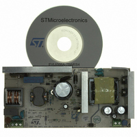
BOARD DEMO FOR L6563/LL6566A
Manufacturer
STMicroelectronics
Type
Power Factor Correctionr
Specifications of EVL6566A-75WES4
Main Purpose
AC/DC, Primary and Secondary Side with PFC
Outputs And Type
1, Isolated
Power - Output
75W
Voltage - Output
19V
Current - Output
4A
Voltage - Input
90 ~ 264VAC
Regulator Topology
Flyback
Board Type
Fully Populated
Utilized Ic / Part
L6563, L6566A, TSM1014
Input Voltage
90 V to 264 V
Output Voltage
19 V
Dimensions
78 mm x 170 mm
Product
Power Management Modules
Lead Free Status / RoHS Status
Lead free / RoHS Compliant
Frequency - Switching
-
Lead Free Status / Rohs Status
Lead free / RoHS Compliant
For Use With/related Products
L6563S, L6566A
Other names
497-8834
Available stocks
Company
Part Number
Manufacturer
Quantity
Price


Functional check
18/37
Figure 15. Transition full load to no load at 265
CH1: Drain voltage
CH2: Vcc
Overcurrent and short-circuit protection
In this demonstration board the overcurrent is managed by TSM1014 (U5), a CC/CV
controller. Inside the IC there are a voltage reference and two Or-ed operational amplifiers,
one dedicated to act as the error amplifier of the voltage loop, the second is dedicated to act
as the error amplifier of the current loop. During normal operation the voltage feedback loop
is working while, in case the output current exceeds the programmed value, the current loop
error amplifier takes over, thus keeping constant the output current.
In case of a dead-short, the current cannot be limited effectively by U5 because the output
voltage drops so it is not powered, therefore the primary controller must manage the failure
condition.
In case of output short, there are two different possible situations that the controller has to
handle. If the coupling between the secondary winding and the auxiliary winding is good
enough, as soon as the output voltage drops, the auxiliary voltage drops as well and the IC
supply voltage falls below the undervoltage lockout threshold, causing the L6566A to
disable. The controller stops switching and remains in the off-state until the voltage on the
Vcc pin decreases below the Vcc restart threshold (5 V). Then, the HV startup turns on and
charges the Vcc capacitor. As soon as the turn-on threshold is reached, the circuit restarts.
If the short is still there, the circuit just attempts to restart but it stops in a few milliseconds.
Restart attempts are repeated indefinitely, until the short is removed. This provides a very
low frequency hiccup working mode (for this board 0.5 Hz), limiting the current flowing at
secondary side (less than 1 Arms) preventing the power supply from overheating, which
could destroy it.
In case the leakage inductance between auxiliary and secondary winding is not negligible,
some spikes on the auxiliary voltage could keep Vcc above the UVLO threshold for a time
long enough to damage the converter. In this case L6566A detects a short-circuit monitoring
the control pins. When the output voltage drops and consequently pin COMP saturates high,
the soft-start capacitor is charged by an internal current source. When the Vss voltage
reaches an internal disable threshold (5 V), the controller stops switching and starts
operating in hiccup mode as described above.
Vac-50 Hz
CH3: Output voltage
CH4: Output current
Doc ID 15447 Rev 3
Figure 16. Transition no load to full load at 265
CH1: Drain voltage
CH2: Vcc
Vac-50 Hz
CH3: Output voltage
CH4: Output current
AN2941
Related parts for EVL6566A-75WES4
Image
Part Number
Description
Manufacturer
Datasheet
Request
R

Part Number:
Description:
BOARD EVAL FOR L6566A
Manufacturer:
STMicroelectronics
Datasheet:

Part Number:
Description:
STMicroelectronics [RIPPLE-CARRY BINARY COUNTER/DIVIDERS]
Manufacturer:
STMicroelectronics
Datasheet:
Part Number:
Description:
STMicroelectronics [LIQUID-CRYSTAL DISPLAY DRIVERS]
Manufacturer:
STMicroelectronics
Datasheet:

Part Number:
Description:
BOARD EVAL FOR MEMS SENSORS
Manufacturer:
STMicroelectronics
Datasheet:
Part Number:
Description:
NPN TRANSISTOR POWER MODULE
Manufacturer:
STMicroelectronics
Datasheet:
Part Number:
Description:
TURBOSWITCH ULTRA-FAST HIGH VOLTAGE DIODE
Manufacturer:
STMicroelectronics
Datasheet:
Part Number:
Description:
Manufacturer:
STMicroelectronics
Datasheet:
Part Number:
Description:
DIODE / SCR MODULE
Manufacturer:
STMicroelectronics
Datasheet:
Part Number:
Description:
DIODE / SCR MODULE
Manufacturer:
STMicroelectronics
Datasheet:
Part Number:
Description:
Search -----> STE16N100
Manufacturer:
STMicroelectronics
Datasheet:
Part Number:
Description:
Search ---> STE53NA50
Manufacturer:
STMicroelectronics
Datasheet:
Part Number:
Description:
NPN Transistor Power Module
Manufacturer:
STMicroelectronics
Datasheet: