EVL6566A-75WES4 STMicroelectronics, EVL6566A-75WES4 Datasheet - Page 5
EVL6566A-75WES4
Manufacturer Part Number
EVL6566A-75WES4
Description
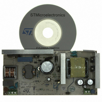
BOARD DEMO FOR L6563/LL6566A
Manufacturer
STMicroelectronics
Type
Power Factor Correctionr
Specifications of EVL6566A-75WES4
Main Purpose
AC/DC, Primary and Secondary Side with PFC
Outputs And Type
1, Isolated
Power - Output
75W
Voltage - Output
19V
Current - Output
4A
Voltage - Input
90 ~ 264VAC
Regulator Topology
Flyback
Board Type
Fully Populated
Utilized Ic / Part
L6563, L6566A, TSM1014
Input Voltage
90 V to 264 V
Output Voltage
19 V
Dimensions
78 mm x 170 mm
Product
Power Management Modules
Lead Free Status / RoHS Status
Lead free / RoHS Compliant
Frequency - Switching
-
Lead Free Status / Rohs Status
Lead free / RoHS Compliant
For Use With/related Products
L6563S, L6566A
Other names
497-8834
Available stocks
Company
Part Number
Manufacturer
Quantity
Price


AN2941
1
Main characteristics and circuit description
The main features of the SMPS are listed as follows:
●
●
●
●
●
●
●
●
●
The circuit is composed of two stages: a front-end PFC using the L6563S and a flyback
converter based on the L6566A. The CV/CC controller TSM1014 allows the correct current
limitation on the secondary side. The flyback stage works as master and it is dedicated to
control the circuit operation including the standby and protections. Additionally, it switches
on and off the PFC stage by means of a dedicated pin (VCC_PFC), thus helping to achieve
an excellent efficiency even at light load, with low complexity.
PFC stage
The main function of the PFC is to keep the current absorbed from the power line tracking
the line voltage to comply with the EN61000-3-2 or other similar regulations and to regulate
the output voltage of the boost stage powering the downstream converter. Therefore, it is
necessary to sense the PFC output voltage as well as the input coming from the mains and
feed these two signals to the controller. The simplest way to implement these functions is to
sense both input and output voltage through two resistor dividers as shown in
These resistors are in the MΩ range (6.6 MΩ for the input divider and 2 MΩ for the output
divider of the example in the figure), however their power dissipation, which is negligible at
full load, becomes significant at light load. Even if the PFC is turned off at light load, the
power dissipation of the two dividers is always there. Additionally, at light load both the input
and the output voltages become very close to the peak value of the rectified mains because
the input and output capacitors act as peak detectors of the rectified mains voltage.
Considering the worst case for power consumption, once the SMPS is working at european
mains range, the power dissipation of these two dividers can be easily calculated as follows:
For example, if we calculate the impact of these losses with a 1 W output load, these two
circuits affect the overall efficiency by about 7%.
Universal input mains range: 90÷264 Vac - frequency 45 ÷ 65 Hz
Output voltage: 19 V at 4 A continuous operation
Mains harmonics: according to EN61000-3-2 Class-D or JEITA-MITI Class-D
Standby mains consumption: < 0.14 W at 230 Vac
Active load average efficiency: better than 87% without synchronous rectification
EMI: according to EN55022-Class-B
Safety: according to EN60950
Dimensions: 78 x 170 mm, 25 mm maximum height of components
PCB: Single-side, 70 µm, CEM-1, mixed PTH/SMT
P
P
MULT
FB
Doc ID 15447 Rev 3
=
=
R
V
R
OUT
MULT
V
MULT
IN
2
2
=
=
(
230
(
230
Main characteristics and circuit description
2
6
V
M
6 .
V
⋅
Ω
M
⋅
2
Ω
2
)
2
)
2
=
=
53
16
mW
mW
Figure 2.
5/37
Related parts for EVL6566A-75WES4
Image
Part Number
Description
Manufacturer
Datasheet
Request
R

Part Number:
Description:
BOARD EVAL FOR L6566A
Manufacturer:
STMicroelectronics
Datasheet:

Part Number:
Description:
STMicroelectronics [RIPPLE-CARRY BINARY COUNTER/DIVIDERS]
Manufacturer:
STMicroelectronics
Datasheet:
Part Number:
Description:
STMicroelectronics [LIQUID-CRYSTAL DISPLAY DRIVERS]
Manufacturer:
STMicroelectronics
Datasheet:

Part Number:
Description:
BOARD EVAL FOR MEMS SENSORS
Manufacturer:
STMicroelectronics
Datasheet:
Part Number:
Description:
NPN TRANSISTOR POWER MODULE
Manufacturer:
STMicroelectronics
Datasheet:
Part Number:
Description:
TURBOSWITCH ULTRA-FAST HIGH VOLTAGE DIODE
Manufacturer:
STMicroelectronics
Datasheet:
Part Number:
Description:
Manufacturer:
STMicroelectronics
Datasheet:
Part Number:
Description:
DIODE / SCR MODULE
Manufacturer:
STMicroelectronics
Datasheet:
Part Number:
Description:
DIODE / SCR MODULE
Manufacturer:
STMicroelectronics
Datasheet:
Part Number:
Description:
Search -----> STE16N100
Manufacturer:
STMicroelectronics
Datasheet:
Part Number:
Description:
Search ---> STE53NA50
Manufacturer:
STMicroelectronics
Datasheet:
Part Number:
Description:
NPN Transistor Power Module
Manufacturer:
STMicroelectronics
Datasheet: