EVL6566A-75WES4 STMicroelectronics, EVL6566A-75WES4 Datasheet - Page 19
EVL6566A-75WES4
Manufacturer Part Number
EVL6566A-75WES4
Description
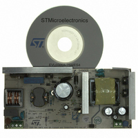
BOARD DEMO FOR L6563/LL6566A
Manufacturer
STMicroelectronics
Type
Power Factor Correctionr
Specifications of EVL6566A-75WES4
Main Purpose
AC/DC, Primary and Secondary Side with PFC
Outputs And Type
1, Isolated
Power - Output
75W
Voltage - Output
19V
Current - Output
4A
Voltage - Input
90 ~ 264VAC
Regulator Topology
Flyback
Board Type
Fully Populated
Utilized Ic / Part
L6563, L6566A, TSM1014
Input Voltage
90 V to 264 V
Output Voltage
19 V
Dimensions
78 mm x 170 mm
Product
Power Management Modules
Lead Free Status / RoHS Status
Lead free / RoHS Compliant
Frequency - Switching
-
Lead Free Status / Rohs Status
Lead free / RoHS Compliant
For Use With/related Products
L6563S, L6566A
Other names
497-8834
Available stocks
Company
Part Number
Manufacturer
Quantity
Price


AN2941
Figure 17. Short-circuit at full load and
CH1: Gate voltage
CH2: Vcc
In
threshold (10 V) causing controller turn-off before the SS pin signal attains the disable
threshold (5 V). This happens because the transformer leakage inductance is very low and
as soon as the output voltage drops, the auxiliary voltage drops immediately as well.
Furthermore from the graph we can note that, during the SS voltage ramp-up, the
transferred power is limited.
Overvoltage and open loop protection
The EVL6566A-75WES4 board implements two different open loop protections, one for
each stage.
The PFC controller L6563S is equipped with an OVP monitoring the output voltage by the
PFC_OK (#7) pin with a resistor divider (R3, R5, R11 high, R10 and R19 low). This divider is
selected so that the voltage at the pin reaches 2.5 V if the output voltage exceeds a preset
value (455 V in this case). When this function is triggered, the gate drive activity is
immediately stopped and it restarts as the voltage on the pin falls below 2.4 V. This function
protects the bulk capacitor from voltage surges caused by abrupt load/line changes or
startup overshoot. Because, in this case no failure occurred, the controller restarts as the
output voltage falls below the overvoltage threshold. However, if the voltage on pin INV falls
40 mV below that of the PFC_OK pin, a feedback failure is assumed. In this case the device
is latched off, its quiescent consumption is reduced below 250 µA and the condition is
latched as long as the supply voltage of the IC is above the UVLO threshold. At the same
time the pin PWM_LATCH (pin #8) is asserted high. This pin is an open source output
intended for tripping a latched shutdown function of the PWM controller IC in the cascaded
DC-DC converter, so that the entire unit is latched off. On this board the PWM_LATCH is
connected to the DIS pin of the L6566A.
230 Vac - 50 Hz
Figure 18
we can see that, in this case, the IC supply voltage drops to the UVLO
CH3: SS pin voltage
CH4: Output current
Doc ID 15447 Rev 3
Figure 18. Short-circuit details at full load and
CH1: Drain voltage
CH2:Vcc
230 Vac - 50 Hz
CH3: SS pin voltage
CH4: Output current
Functional check
19/37
Related parts for EVL6566A-75WES4
Image
Part Number
Description
Manufacturer
Datasheet
Request
R

Part Number:
Description:
BOARD EVAL FOR L6566A
Manufacturer:
STMicroelectronics
Datasheet:

Part Number:
Description:
STMicroelectronics [RIPPLE-CARRY BINARY COUNTER/DIVIDERS]
Manufacturer:
STMicroelectronics
Datasheet:
Part Number:
Description:
STMicroelectronics [LIQUID-CRYSTAL DISPLAY DRIVERS]
Manufacturer:
STMicroelectronics
Datasheet:

Part Number:
Description:
BOARD EVAL FOR MEMS SENSORS
Manufacturer:
STMicroelectronics
Datasheet:
Part Number:
Description:
NPN TRANSISTOR POWER MODULE
Manufacturer:
STMicroelectronics
Datasheet:
Part Number:
Description:
TURBOSWITCH ULTRA-FAST HIGH VOLTAGE DIODE
Manufacturer:
STMicroelectronics
Datasheet:
Part Number:
Description:
Manufacturer:
STMicroelectronics
Datasheet:
Part Number:
Description:
DIODE / SCR MODULE
Manufacturer:
STMicroelectronics
Datasheet:
Part Number:
Description:
DIODE / SCR MODULE
Manufacturer:
STMicroelectronics
Datasheet:
Part Number:
Description:
Search -----> STE16N100
Manufacturer:
STMicroelectronics
Datasheet:
Part Number:
Description:
Search ---> STE53NA50
Manufacturer:
STMicroelectronics
Datasheet:
Part Number:
Description:
NPN Transistor Power Module
Manufacturer:
STMicroelectronics
Datasheet: